- SIGNA™ Hero 3.0T Service Methods
- 5852800-8EN Revision 1.0
- 00000018WHA30FB62GYZ
- id_200143711.3
- Oct 5, 2021 10:15:03 AM
Adjusting RF amplifier output power for body channel 1
Procedure
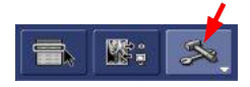
- On the front of the exciter, make sure the RF ENB switch is set to the enabled (up) position.
Figure 1. Exciter switch 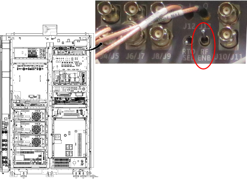
- Select values for the following settings within the tool:
Figure 2. UPM body mode channel 1 settings (For system running PX29.0 or earlier)
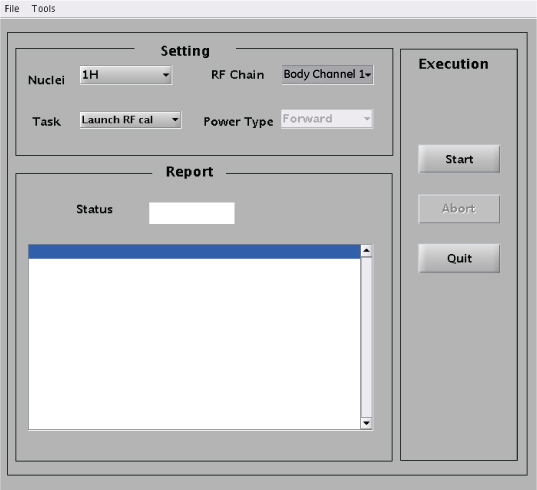
Setting Value Nuclei 1H Task Launch RF Cal RF Chain Body Channel 1 Note: The Power Type drop-down menu is inactive for this step.Figure 3. RF Amp and Power Monitor (RAP) Tool body mode channel 1 settings (For system running PX29.1 or later)
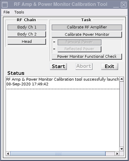
Setting Value Task Calibrate RF Amplifier RF Chain Body Channel 1 - When a dialog box shows, do not click Success or Failure at this time. Instead, navigate to the Scan Desktop.
Figure 4. RF Amp Calibration dialog box 
- From the Scan Desktop, click on the patient icon to navigate to the Scan Workplace.
Figure 5. Patient Icon 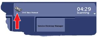
- In the Prescan Looping window, slowly move the Transmit Gain (TG) slide to 100.Note: For all the Transmit Gain (TG) adjustment steps given in this procedure, after the TG slider is set and released in the Prescan Looping window, make sure that the setting is retained by the system (for example the slider does not move back to some other TG setting) prior to executing the next step in the procedure. If the setting was not retained, move the TG slider to the desired setting again and make sure of the setting.
Figure 6. Prescan Looping Window 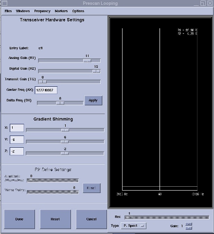
- Make sure the wattmeter reading is more than 1 kW and less than 9.5 kW.
- If the reading is zero or very low:
- Make sure the correct center frequency value.
- Click Done to stop looping and recheck the test setup cabling.
- If the reading exceeds 9.5 kW, slowly adjust the CH1/HD gain adjust on the front panel of the RF amp to 9.5 kW watts for body channel 1.
Figure 7. Gain Adjust 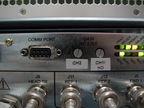
- If the amplifier trips, reset TG to the highest setting it reached before tripping.
Note: If the manual prescan must be stopped and restarted, you must relaunch the calibration sequence using the UPM/RAP tool. Click Failure in the calibration dialog box and then click Start on the UPM/RAP tool with the same menu selections to relaunch the calibration sequence. - If the reading is zero or very low:
- From the Scan Desktop, click on the CSD icon.
Figure 8. CSD icon