
- SIGNA™ Hero 3.0T Service Methods
- 5852800-8EN Revision 1.0
- 00000018WIA30CE1E20GYZ
- id_131067493.0
- Aug 29, 2019 1:40:20 AM
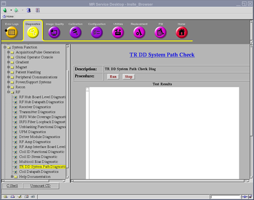
TR DD system path check
Diagnostic link
Diagnostics >> System Function >> RF >> TR DD System Path Diagnostic
Purpose
The purpose of this diagnostic is to help the field engineer in troubleshooting faults related to the T/R (Transmit Receive) and DD (Dynamic Disable & Direct Drive) System Paths.
Components tested
T/R and DD system paths
Requirements
- Ensure no scan is running before running the diagnostic.
- To test all failure modes, each type of transmit coil or switch that could be used in the system must be tested. This includes Connector A local transmit proton coils, Connector P1 local transmit proton coils, and Connector A MNS transmit switches.
- Only one coil or transmit switch can be connected at a time. This means that the diagnostic must be executed multiple times on differing coil/switch populations to fully cover all failure scenarios.
- Insert service key.
Test Sequence
- Disconnect all local transmit coils and MNS T/R switches from Connectors A and P1.
- Click Run to start the diagnostic.Note: Click Stop to halt the diagnostic.
Block diagram
None
Expected results
The results are displayed in the test results window. The results are also logged under /usr/g/service/log/System_Path_Diag_Log.txt.
If the diagnostic completes without errors, no further action is required.
If a failure occurs, review the diagnostic error message in the results window, as well as the system error log and extended error messages for subsequent actions. The error message will state the problem and what signal path is experiencing it.
- If a Connector A local transmit proton coil will be used with the system, connect it to Connector A. Click Run to begin diagnostic again.
- If a Connector P1 local transmit proton coil will be used with the system, connect it to Connector P1. Click Run to begin diagnostic again.
- If the system is MNS enabled and a MNS T/R switch will be used with the system, connect it to Connector A. Click Run to begin diagnostic again.
This diagnostic has the ability to detect the following faults:
| T/R Faults | DD Faults |
| Head: Open & Short | Open |
| Body: Open & Short | Short |
| MNS: Open & Short (optional) | High Voltage |
| Head and Body Cables Swapped | - |
| MNS and Body Cables Swapped (optional) | - |
| MNS and Head Cables Swapped (optional) | - |
| Connector A and Connector P1 T/R Cables Swapped | - |