
- SIGNA™ Hero 3.0T Service Methods
- 5852800-8EN Revision 1.0
- 00000018WIA30D7CE20GYZ
- id_131058773.4
- Feb 3, 2021 2:26:09 PM
3.0T split-top head coil FRUs and replacement
Personnel Requirements
| Required Persons | Procedure Timing |
| 1 | 30 minutes |
Procedure Overview
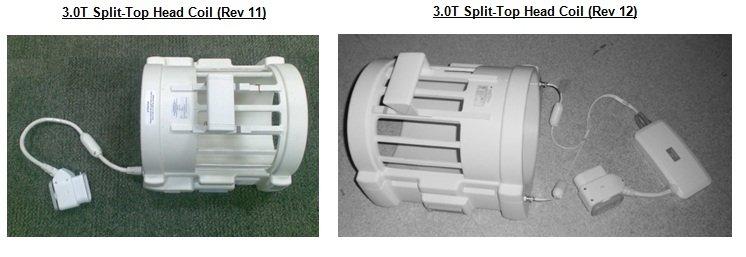
This document contains replacement procedures and lists the FRUs for the 3.0T Split-Top Head Coil by GE BGL. Review the list of coil FRUs and other accessories before replacing the external cable and mechanical hardware of the coil. Run SNR check after any FRU replacement to confirm the coil performs per specifications.
FRUs and Other Accessories
| Description | GE Part Number |
| 3.0T Head Coil Birdcage (for Rev 12 and later - Coil only) | 5450630 |
| MR 750 3.0T Head Coil and QHTR FRU | 5436083 |
| QHTR I/F Cable Assembly (for Rev 12 and later) | 5437386 |
| Head Coil Latching FRU Kit (for Rev 12 and later) | 5191687 |
| Spring Contact | 2355094 |
| P9364FC Mirror | 2145391 |
| 3.0T Small Footprint Preamp FRU Kit (for Rev 7 and later) | 5433509 |
| Description | GE Part Number |
| 3.0T Head Coil Cable Assembly FRU Kit, HDv (for coil Rev 1 through Rev 11 only) | 5269301 |
| 3.0T Head Coil TR PCB Assembly FRU Kit, HDv (for coil Rev 7 through Rev 11 only) | 5366299 |
| Description | GE Part Number |
| Cushion Head - Split Head Coil, HDv | 5327302 |
| Head Coil Flat Cushion, HDv | 5327301 |
| Kit Head Restraint Straps | 2352202 |
| Description | MR System | GE Part Number |
|---|---|---|
| Adapter Assembly for SIGNA Pioneer and Premier - Transmit/Receive Split Head Coil | Pioneer, Premier | 5821371 |
| Curved Adapter Panel for Flat Table (GEM) | Architect, 750w GEM | 5395828 |
Preliminary Requirements
Tools and Test Equipment
The following tools are required for this procedure:
-
Standard tool kit
-
Flat-blade screwdriver
-
Digital multi-meter (DMM)
Replacement Parts
-
3.0T Small Footprint Preamp FRU Kit, P/N 5433509 (contains Preamp P/N 2409871)
-
Head Coil Latching FRU Kit (for Rev 12 and later), P/N 5191687
-
3.0T Split-Top Head Coil TR PDB Assembly FRU Kit, HDv P/N 5366299 (contains TR PWA P/N 6300158)
-
Part of 3.0T Split-top Head Coil Cable Assembly FRU Kit, HDv, P/N 5269301 (contains cable assembly P/N 5182567)
-
Spring Contacts Replacement Kit - 2355094
Procedure
External Cable Replacement (P/N 5269301 for Rev 1 through Rev 11)
-
Remove the head coil top from the head coil bottom.
-
Unscrew the five brass screws (No. 45) and nine nylon screws (No. 29) with nylon washers (No. 32) from the head coil bottom cover plate.
Figure 2. 3.0T Split-Top Head Coil Bottom Cover Plate 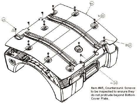
-
Remove the head coil bottom cover plate from the bottom of the head coil.
-
Unscrew the two M3 x 8 screws (No. 51) from the TR board secured to the head coil bottom.
Figure 3. Connectors on TR Board 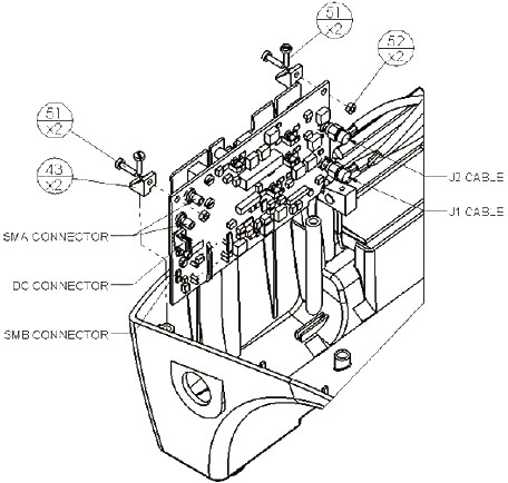
-
Lift the TR board and while holding it outside of the coil, disconnect the cable from the board.
-
Remove the two SMA straight crimp-type plugs from the RG58 cable using the appropriate spanner.
-
Unplug the SMB RG174 straight cable crimp and female DC connector on the cable assembly.
-
-
Remove the sealing nut from the cable strain relief (P/N 5248402) using the appropriate spanner.
-
Pull and remove the cable from the head coil, and reposition the TR board.
-
To reconnect the cable assembly to the TR board:
-
Insert the cable through the opening in the housing.
-
Lift the TR board, and hold it outside of the coil.
-
Connect the two SMA straight crimp-type plugs for the RG58 cable to the TR board. Tighten until snug, but do not overtighten.
-
Insert the SMB RG174 straight cable crimp and the female DC connector on the cable assembly into the TR board.
-
-
Insert the TR board into the head coil, and secure it to the head coil bottom with two M3 x 8 screws (No. 51 in Figure 3). Tighten the screws until snug, but do not overtighten.
-
Using the appropriate spanner, tighten the sealing nut of the cable strain relief until it is snug, but do not overtighten.
-
Replace the head coil bottom cover plate (No. 44).
-
Secure it with the five brass screws (No. 45) and nine nylon screws (No. 29) with nylon washers (No. 32) shown in Figure 2.
-
Tighten the screws until snug, but do not overtighten.
-
-
Reattach the head coil top to the head coil bottom.
-
Perform a test scan with the head coil to verify operation.
TR Board Replacement (P/N 5366299 for Rev 7 through Rev 11)
-
Remove the head coil top from the head coil bottom.
-
From the head coil bottom, unscrew five brass screws (No. 45) and nine nylon screws (No. 29) with nylon washers (No. 32) shown in Figure 2.
-
Remove the head coil bottom cover plate from the bottom of the head coil.
-
Unscrew the two M3 x 8 screws (No. 51) from the TR board secured to the head coil bottom shown in Figure 3.
-
Disconnect the J1 and J2 cables from the TR board.
Figure 4. Cable Assembly on 3.0T Split-Top Head Coil 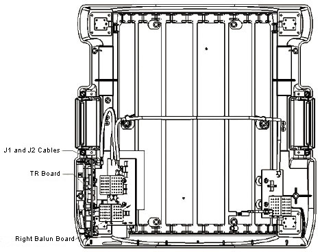
-
Lift the TR board out, and while holding it outside of the coil, disconnect the cable from the board.
-
Remove the two SMA straight crimp-type plugs from the RG58 cable using the appropriate spanner.
-
Unplug the SMB RG174 straight cable crimp and the female DC connector on the cable assembly from the TR board. (See Figure 3.)
-
-
To reinstall the TR board:
-
Reconnect the two SMA straight crimp-type plugs for the RG58 cable to the TR board.
-
Plug the SMB RG174 straight cable crimp and the female DC connector on the cable assembly (P/N 5182567) into the TR board.
-
Tighten the screws until snug, but do not overtighten.
-
-
Connect the J1 and J2 cables to the TR board.
-
Insert the TR board into the head coil bottom, and secure using two M3 x 8 screws (No. 51) shown in Figure 3. Tighten the screws until snug, but do not overtighten.
-
Position the head coil bottom cover plate onto the bottom of the head coil with five brass screws (No. 45) and nine nylon screws (No. 29) with nylon washers (No. 32) shown in Figure 3. Tighten the screws until snug, but do not overtighten.
-
Reattach the head coil top to the head coil bottom.
-
Perform a test scan with the coil to verify operation.
Preamplifier Replacement (P/N 5433509)
Replace Preamplifier in QHTR Interface Box (Rev 12 onwards)
-
Remove the top cover of the head coil QHTR interface box.
-
To remove the defective preamplifier, cut the tie wrap securing the preamplifier.
Figure 5. Preamplifier with Tie Wrap 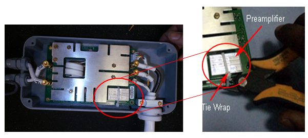
-
Use a flat-blade screwdriver to lift the preamplifier from QHTR interface board.
Figure 6. Remove Preamplifier with Screwdriver 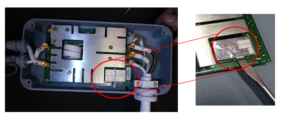
-
Install the new preamplifier on the QHTR interface board. Secure it with a tie wrap. Cut and remove the excess length of the tie wrap.
-
Replace the top cover of the head coil QHTR interface box.
-
Perform a test scan with the coil to verify operation.
Replace Preamplifier in Head Coil TR (Rev 7 through Rev 11)
-
Remove the head coil top from the head coil bottom.
-
From the head coil bottom, unscrew 5 brass screws (No. 45) and 9 nylon screws (No. 29) with nylon washers (No. 32) shown in Figure 2.
-
Remove the head coil bottom cover plate from the bottom of the head coil.
-
Unscrew the two M3 x 8 screws (No. 51) from the TR board secured to the head coil bottom shown in Figure 3
-
Disconnect the J1 and J2 cables from the TR board (all shown in Figure 4).
-
Lift the TR board out, and while holding it outside of the coil, disconnect the cable from the TR board.
-
Remove the two SMA straight crimp-type plugs for the RG58 cable using the appropriate spanner.
-
Unplug the SMB RG174 straight cable crimp and the female DC connector on the cable assembly from the TR board. (See Figure 3.)
-
Remove the TR board outside of the coil.
-
Check the health of pin diodes (D1, D2, D3, D4, D5) using a digital multi-meter (in Diode Test mode). In forward bias, the DMM should show values between 400 and 700; in reverse bias, it should show open.
-
If the DMM shows any short (beep sound or very low value, <400, in forward bias), the pin diodes are damaged. Replace the TR board assembly (P/N 5366299).
-
If all pin diodes are good (both in forward and reverse bias), replace only the preamplifier (P/N 5433509).
-
-
-
To remove the defective preamplifier, cut and remove the tie wrap securing the preamplifier to the TR board.
Figure 7. Tie Wrap Holding Preamplifier to TR Board 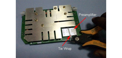
-
Use a flat-blade screwdriver to lift the preamplifier from the TR board.
Figure 8. Remove Preamplifier with Screwdriver 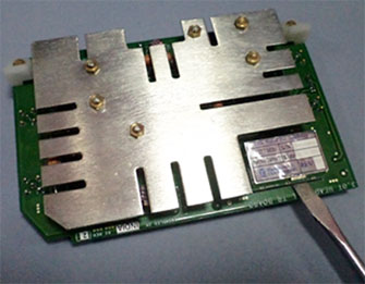
-
Install the new preamplifier in the same location. Secure it with a tie wrap. Cut and remove the excess length of the tie wrap.
-
Reconnect the two SMA straight crimp-type plug for the RG58 cable to the TR board.
-
Plug the SMB RG174 straight cable crimp and the female DC connector on the cable assembly (P/N 5182567) into the TR board.
-
Tighten the screws until snug, but do not overtighten.
-
Connect the J1 and J2 cables to the TR board.
-
Insert the TR board into the head coil bottom, and secure using two M3 x 8 screws (No. 51). Tighten the screws until snug, but do not overtighten. (See Figure 3.)
-
Position the head coil bottom cover plate onto the bottom of the head coil with five brass screws (No. 45) and nine nylon screws (No. 29) with nylon washers (No. 32) shown in Figure 3. Tighten the screws until snug, but do not overtighten.
-
Reattach the head coil top to the head coil bottom.
-
Perform a test scan with the coil to verify operation.
Head Coil Latching FRU Kit P/N 5191687 (Head Coil Rev 12 onwards)
The contents of Head Coil Latching FRU Kit are:
| P/N | Description |
| 2347569 | Nylon Screw Pan Head M4 x 8, Qty 10 |
| 2308715 | Bottom Cover Plate, Qty 1 |
| 2382710 | Pivot Block, Qty 4 |
| 2347569-2 | Nylon Screw Pan Head M4 x 12, Qty 4 |
| 2358535-3 | Slotted Flat Head Screw Brass M4 x 10, Qty 4 |
| 46-214941P2 | Nylon Plane Washer, Qty 10 |
The only tool required in these procedures is a slot-head screwdriver.
-
Remove the bottom cover plate of the head coil by removing 10 nylon screws and 4 brass screws. (Discard the disassembled bottom cover plate)
Figure 9. Remove Screws from Bottom Cover Plate 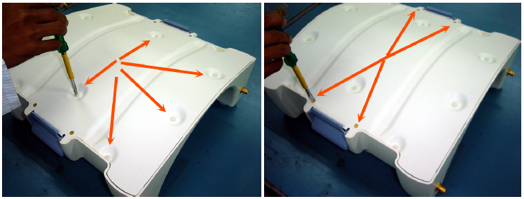
-
Remove the head coil latch and pivot blocks by removing the nylon screws. (Discard the disassembled pivot blocks.)
Figure 10. Remove Latch and Pivot Blocks 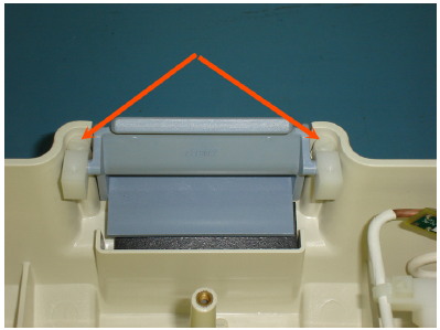
-
Insert two new pivot blocks (2382710, supplied in FRU kit) on the latch and mount the screws.
Figure 11. Install New Pivot Blocks 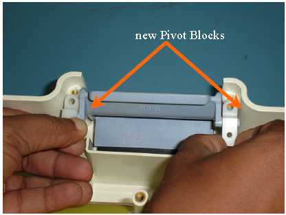
-
Repeat the steps above on the second head coil latch.
-
Fix the new bottom cover plate (2380715, supplied in FRU kit) with nylon screws and brass screws. Ensure free movement of the latch assembly.
Figure 12. New Bottom Cover Plate 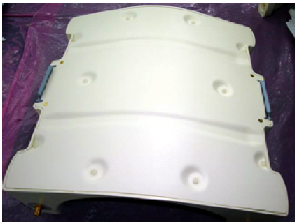
Spring Clip Replacement
-
The four spring clip connectors are located in the head coil baseplate, under the plastic caps (marked A in the illustration below).
Figure 13. Four Spring Clip Connectors 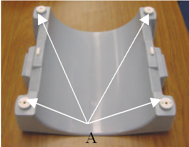
-
Remove the plastic caps by removing the two screws (marked B in the illustration below).
Figure 14. Remove Plastic Caps 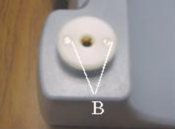
-
Remove the gold spring clip and red gasket.
Figure 15. Remove Gold Spring Clip and Red Gasket 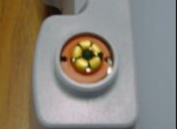
-
Install the new spring clip.
Figure 16. Install New Spring 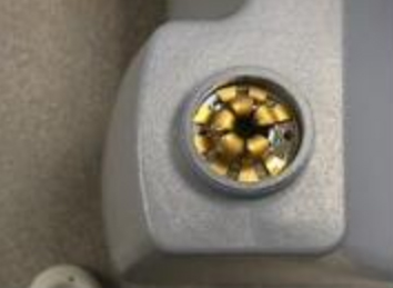
-
Insert the red gasket and replace the plastic cap.