
- Discovery MR750 3.0T System Service Methods
- 5690009-2EN Revision 4
- 00000018WIA30751E20GYZ
- id_131075364.0
- Feb 21, 2021 9:07:49 PM
XRFD and power supply replacement
Prerequisites
| Required persons | Preliminary requirements | Procedure | Finalization |
|---|---|---|---|
| 1 | 5 minutes | 90-120 minutes | 5 minutes |
| Item | Quantity | Effectivity | Part number | Manufacturer |
|---|---|---|---|---|
| Hoist Service Kit | 1 | - |
5196226 | - |
| Non-Magnetic Tool Kit (or equivalent) | 1 | - |
5113258 | - |
| Item | Quantity | Effectivity | Part number | Manufacturer |
|---|---|---|---|---|
| Towels | N/A | - | - | - |
| Tie wraps | 3-5 | - | - | - |
| Item | Quantity | Effectivity | Part number | Manufacturer |
|---|---|---|---|---|
| XRFD | 1 | - |
5135844-3 | - |
| XRFD Power Supply | 1 | - |
5135844-4 | - |
| ||||
| Condition | Reference | Effectivity |
|---|---|---|
| The PGR PDU/gradient subsystem must be locked and tagged out before starting this procedure. See the MR Service Safety Manual, PN 5452735. | - | - |
| Before disconnecting any coolant lines on the front of the XRFD unit, shut down the PPMP at the HEC. | - | - |
About this task
This document contains four procedures (two for each style of cabinet): XRFD replacement and XRFD power supply replacement. Both units are in the PGR cabinet. The XRFD weighs about 315 pounds and the XRFD PS weighs 80 pounds. Each unit weighs enough that a hoist kit is required. This document details the correct way to use a hoist kit to safely remove and replace the XRFD and XRFD PS units.
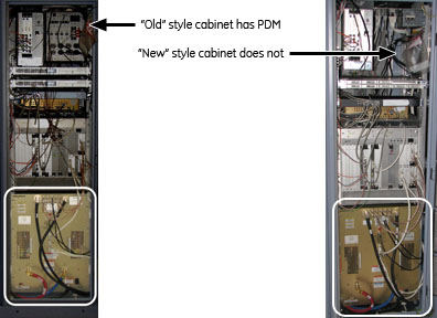
Choose appropriate instruction
About this task
XRFD replacement (with PDM)
Procedure
- Before setting up the hoist kit, detach the XPS J9 connector
to properly remove the main lifting beam.
Figure 2. Lifting beam and connector in PGR cabinet 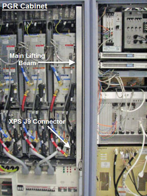
- Remove the tie wraps that hold the power cable. The cable goes
underneath the XRFD and along the side of the cabinet to the top of
the PDM.
Figure 3. Tie Wraps on Power Cable 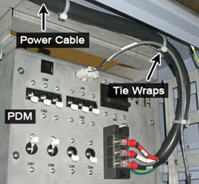 Note: Before continuing, be prepared to absorb any leakage from the coolant lines with a towel in hand as the line is disconnected.
 - Disconnect the power cable at the terminal, the cables on the
front of the XRFD, and the coolant lines. Carefully move the cables
and lines to the side of the cabinet, so the surrounding area is free
from any obstructions when the amplifier is pulled out.
Figure 4. Coolant lines placement 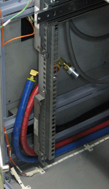
- Unscrew the eight attachment screws.
Figure 5. XRFD attachment screws 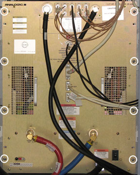
- Attach the lifting brackets (found in the XRFD FRU crate) to
both sides of the XRFD. The attachment screws are captive screws and
remain with the lifting brackets.
Figure 6. Inside FRU Crate - Lifting Brackets 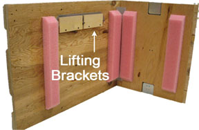
- Hook the winch and spreader bar from the hoist kit to the lifting
bracket. Ratchet the winch to tighten the chain.Note: Make sure the hook is seated in the lifting bracket. If not, the weight can shift causing harm to the equipment or the engineer.
Figure 7. Lifting brackets with seated hook 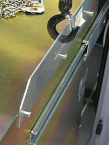
- With the XRFD unit supported by the hoist kit, unscrew the four
screws and remove the slide rails from both sides.
Figure 8. XRFD Slide Rails 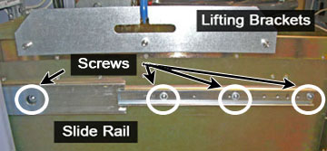
- The FRU is packaged in a wooden crate. For the XRFD, there are
four parts to the FRU crate. Remove the top of the wooden crate and
turn it on its base. The XRFD being removed can be placed into the
top. Roll the top underneath the XRFD and lock the wheels so that
the container does not move.
Figure 9. Base of FRU crate 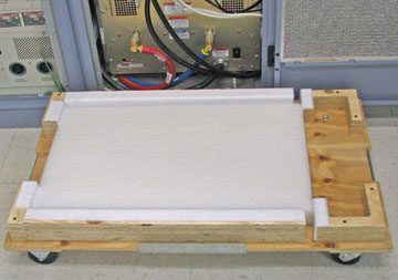
- Remove the shipping screw from each side of the XRFD FRU.
Figure 10. Shipping Screw on XRFD FRU 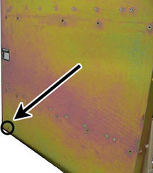
- Bring the FRU to the front of the cabinet. Attach the slide
rails to the FRU.
Figure 11. XRFD FRU 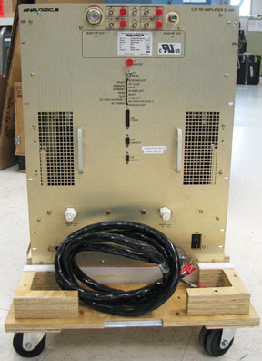
XRFD Power supply replacement (with PDM)
Procedure
- Unscrew the eight large screws that attach the XRFD to the cabinet,
the four screws that attach to the manifold, the twenty-two faceplate
screws, and the two BNC locking nuts.
Figure 12. XRFD - all Sscrews 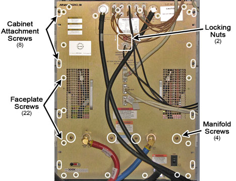
- Remove the XRFD PS faceplate. After the faceplate is pulled away from the unit, do the following steps:
- Lift the manifold tray and pull it out of the way of the power supply. The manifold has a spring loaded pin that allows the tray to swivel up and down.
Figure 13. Manifold Pin on XRFD PS 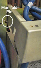
- Note: If the supply does not slide forward, extend the XRFD from the cabinet and check that the shipping screws have been removed from each side of the XRFD.Remove the two sub-D cables, PSU-1 and PSU-2.
Figure 14. Sub-D cables 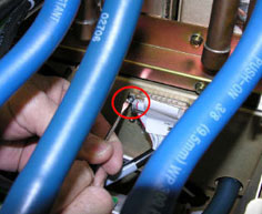
- Lift the manifold tray and pull it out of the way of the power supply. The manifold has a spring loaded pin that allows the tray to swivel up and down.
- Hook the winch and spreader bar from the hoist kit to the lifting
bracket. Ratchet the winch to tighten the chain.Note: Make sure the hook is seated in the lifting bracket. If not, the weight can shift causing harm to the equipment or the engineer.
Figure 15. XRFD PS with hoist kit 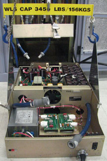
XRFD replacement (without PDM)
Procedure
- Before setting up the hoist kit, detach the XPS J9 connector
to properly remove the main lifting beam.
Figure 16. Lifting beam and connector in PGR cabinet - Note: Before continuing, be prepared to absorb any leakage from the coolant lines with a towel in hand as the line is disconnected.Disconnect the cables on the front of the XRFD, and disconnect the coolant lines. Carefully move the cables and lines to the side of the cabinet, so the surrounding area is free from any obstruction when the amplifier is pulled out.
Figure 17. Coolant lines placement - Remove the PGR base plate by unscrewing the two attached screws.
Figure 18. PGR Base Plate 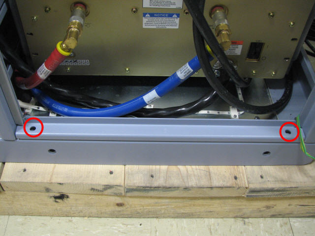
- Unscrew the eight attachment screws.
Figure 19. XRFD attachment screws - Attach the lifting brackets (found in the FRU crate) to both
sides of the XRFD. The attachment screws are captive screws and remain
with the lifting brackets.
Figure 20. Inside FRU crate - lifting brackets - Hook the winch and spreader bar from the hoist kit to the lifting
bracket. Ratchet the winch to tighten the chain.Note: Make sure the hook is seated in the lifting bracket. If not, the weight can shift causing harm to the equipment or engineer.
Figure 21. Lifting brackets with seated hook - With the XRFD unit supported by the hoist kit, unscrew the four
screws and remove the slide rails from both sides.
Figure 22. XRFD slide rails - The FRU is packaged in a wooden crate. For the XRFD, there are
four parts to the FRU crate. Remove the top of the wooden crate and
turn it on its base. The XRFD being removed can be placed into the
top. Roll the top under the XRFD and lock the wheels so that the container
does not move.
Figure 23. Base of FRU Crate - Disconnect the XRFD power cable from the terminal.
Figure 24. XRFD terminal block 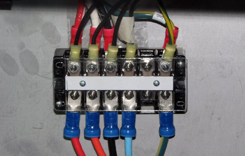
- Remove the shipping screw from each side of the XRFD FRU.
Figure 25. Shipping screw on XRFD FRU - Bring the FRU to the front of the cabinet. Attach the power
cable to the terminal and attach the slide rails to the FRU.
Figure 26. XRFD FRU
XRFD power supply replacement (without PDM)
Procedure
- Unscrew the eight attachment screws.
Figure 27. XRFD attachment screws - Attach the lifting brackets (found in the FRU crate) to both
sides of the XRFD. The attachment screws are captive and remain with
the lifting brackets.
Figure 28. Inside FRU crate - lifting brackets - Hook the winch and spreader bar from the hoist kit to the lifting
bracket. Ratchet the winch to tighten the chain. Note: Make sure the hook is seated in the lifting bracket. If not, the weight can shift, causing harm to the equipment or engineer.
Figure 29. Lifting brackets with seated hook - Disconnect the XRFD power cable from the terminal and bring
to the front of the XRFD.
Figure 30. XRFD terminal block - Unscrew the four screws that attach to the manifold, the twenty-two
faceplate screws, and the two BNC locking nuts.
Figure 31. XRFD - all screws - Remove the XRFD PS faceplate. After the faceplate is pulled away from the unit, do the following steps:
- Lift the manifold tray and pull it out of the way of the power supply. The manifold has a spring loaded pin that allows the tray to swivel up and down.
Figure 32. Manifold Pin on XRFD PS - Note:Remove the two sub-D cables, PSU-1 and PSU-2.
If the supply does not slide forward, extend the XRFD from the cabinet and check that the shipping screws have been removed from each side of the XRFD.
Figure 33. Sub-D cables
- Lift the manifold tray and pull it out of the way of the power supply. The manifold has a spring loaded pin that allows the tray to swivel up and down.
- Hook the winch and spreader bar from the hoist kit to the lifting
bracket. Ratchet the winch to tighten the chain.Note: Make sure the hook is seated in the lifting bracket. If not, the weight can shift causing harm to the equipment or the engineer.
Figure 34. XRFD PS with hoist kit - Hook the winch and spreader bar from the hoist kit to the lifting
bracket. Ratchet the winch to tighten the chain.Note: Make sure the hook is seated in the lifting bracket. If not, the weight can shift, causing harm to the equipment or the engineer.
Figure 35. Seated hook - Attach the XRFD power cable to the terminal block.
Figure 36. XRFD terminal block