- Discovery MR750 3.0T System Service Methods
- 5690009-2EN Revision 4
- 00000018WIA30702750GYZ
- id_20255472.7
- Jan 25, 2022 3:03:44 PM
Setting up the laser level for measurements
Procedure
- Attach the laser level (5831466) to the coupling on the tripod (5829559) and turn on the vertical and horizontal laser lines.
Figure 1. Laser level toggles 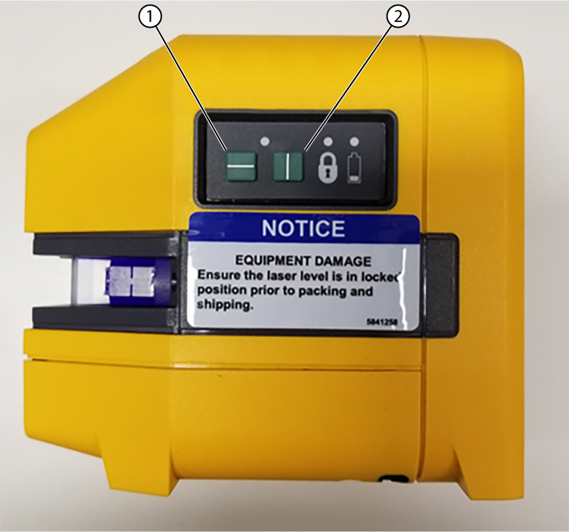
1 Horizontal laser line 2 Vertical laser line - Make sure the laser level in is self-leveling mode.
Figure 2. Laser level in self-leveling mode 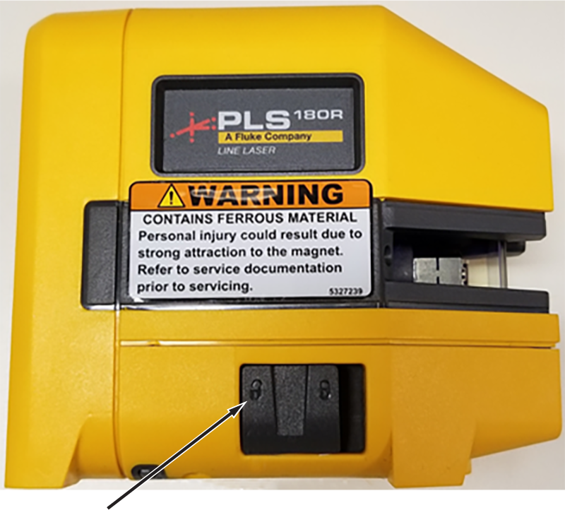
- Set the laser level height on the tripod such that the horizontal laser line can be seen above the LPCA in the rear of the scan room. Accuracy is not important for the height of the laser level.
Figure 3. Laser level and tripod set up at the front of the MR suite 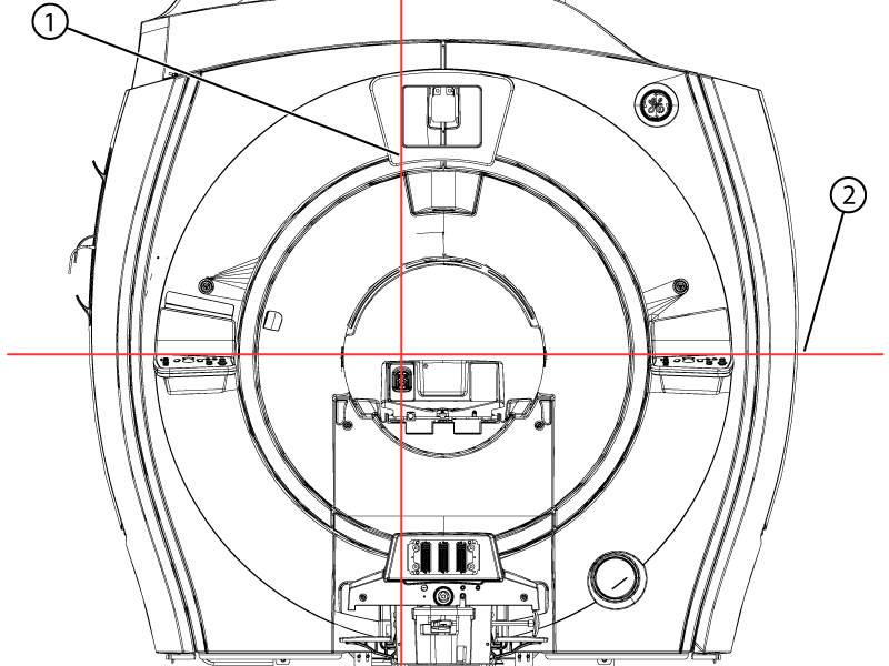
1 Vertical laser line 2 Horizontal laser line
Laser alignment
About this task
Note: The thickness of the laser line can span up to 2 mm depending on the distance from the laser level/tripod to the measurement point. Make sure to consistently measure the same laser line location on the scale.
Note: For the first measurements, it is useful to turn off the horizontal laser line and use only the vertical laser line.
Note: Always measure approximately 100 mm away from the edge of the bridge and the tabletop to avoid the profile changes of the parts.
Procedure
- Put the Horizontal Alignment Laser Target Tool (5830232) on the left side at the front of the bridge.
Figure 4. Horizontal targets on the bridge 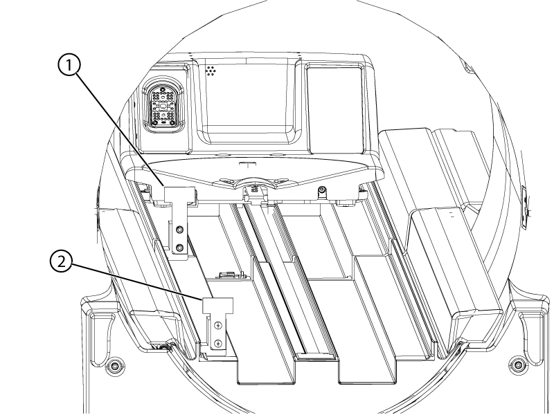
1 Tall target (5830232-2) 2 Short target (5830232) Note: Early bridges may have machined channels for the rolling surface. These surfaces may prevent the tool from sitting level. The vertical rulers can be removed from their bases and used under the tool to correct.Figure 5. Vertical ruler used to level horizontal ruler base 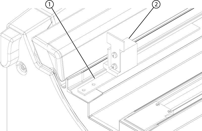
1 Vertical ruler 2 Horizontal ruler Note: Make sure the tool is assembled correctly. The bottom and side edges of the ruler must be against the bottom and side lips of the tool base. If the edges are not properly aligned, loosen the screws and adjust the ruler. Tighten the screws after adjustment or if they are loose.Figure 6. Horizontal ruler adjustment 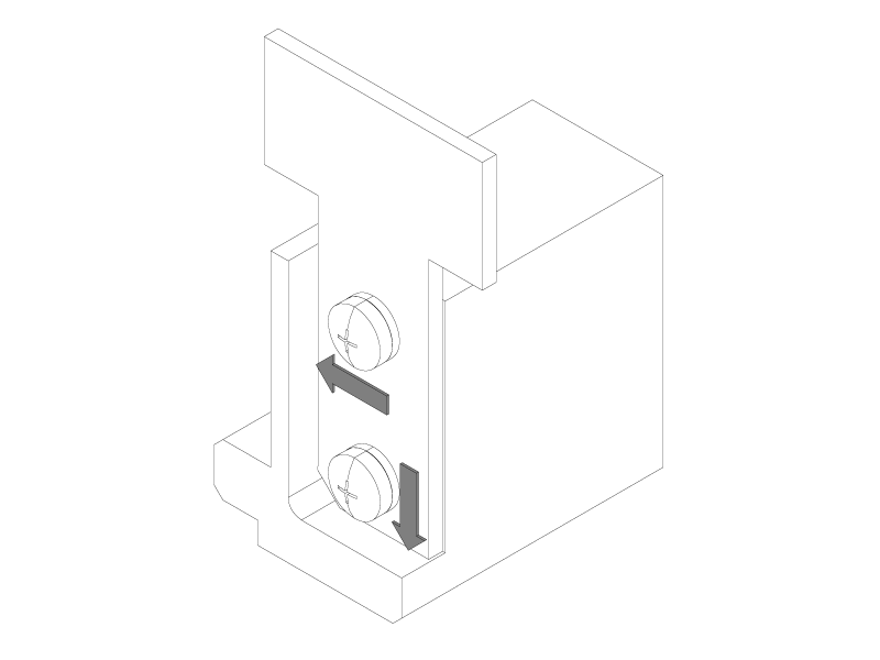
- Align the laser level and tripod such that the vertical laser line is approximately parallel to the bridge and strikes the short and tall targets along the horizontal scale.
Figure 7. Vertical laser line on short and tall horizontal targets 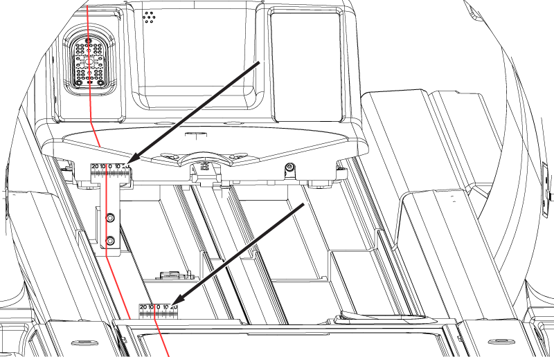
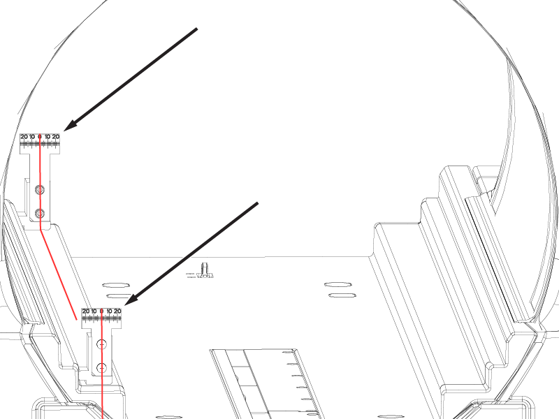
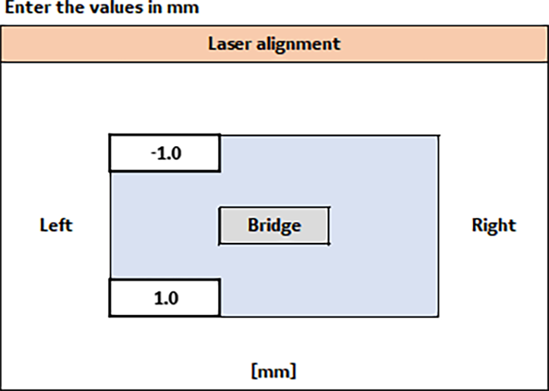
- Record the values the laser line strikes through on the short and tall targets in millimeters. Acceptance criteria for aligning the vertical laser line is between -5 and 5 mm.Note: Make sure to capture if the number is positive or negative. The vertical laser line intersecting a number to the left of the zero on the scale is negative and to the right of the zero on the scale is positive.Note: These values are used as a datum reference plane for the following alignments. It is helpful to mark two locations, at the front and rear of the room along the vertical laser line in case the laser level is bumped or moved.
Figure 8. Sample laser alignment values in the macro tool