
- Discovery MR750 3.0T System Service Methods
- 5690009-2EN Revision 4
- 00000018WIA3047AE20GYZ
- id_131075383.1
- Oct 11, 2021 8:47:14 PM
Operator Display and Control Panels Replacement
Prerequisites
| Required persons | Preliminary requirements | Procedure | Finalization |
|---|---|---|---|
| 1 | 5 minutes | 45 minutes | 5 minutes |
| Item | Quantity | Effectivity | Part number | Manufacturer |
|---|---|---|---|---|
| Non-Magnetic Tool Kit | 1 | - |
5112581 | - |
| Item | Quantity | Effectivity | Part number | Manufacturer |
|---|---|---|---|---|
| In-Room Display (option) | 1 | - |
See FRU Manual | - |
| Trackball Control Panel (option) | 1 | - |
See FRU Manual | - |
| E-Stop Panel | 1 | - |
See FRU Manual | - |
| Standard Right Control Panel | 1 | - |
See FRU Manual | - |
| Standard Left Control Panel | 1 | - |
See FRU Manual | - |
| ||||
About this task
This document provides the procedures for replacing operator control/display hardware in the front magnet enclosure. This document covers both the in-room display (IRD) version and the version without the IRD.
Replacing In-Room Display
Procedure
- Note:Remove the laser light cover. It is held in place by two screws and a popper.
The PDU must be powered down completely to prevent damage to system electronics.
Figure 1. In-Room Display (IRD) 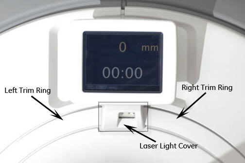
Figure 2. Removing Laser Light Cover 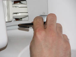
- Remove top panel on back of the IRD by popping tabs with a small
flat head screwdriver.
Figure 3. Removing IRD 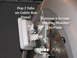
Replacing Trackball Control Panels and E-Stop Button
Procedure
- Note:Remove the front panels. See Front Cover Removal and Installation.
The PDU must be powered down completely to prevent damage to system electronics.
Figure 4. Removing Front Cover 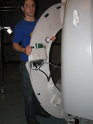
- Disconnect the two cables that connect the control panels to
the magnet enclosure.Note:
If cable connectors are not labeled with a J number, mark the applicable J number on each cable connector before removal.
Figure 5. Removing Control Panel Cables 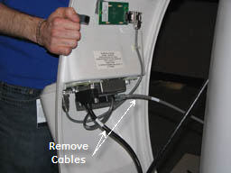
Remove the trackball control panel by removing five screws and detaching the emergency stop (e-stop) button cable.Warning Figure 6. Removing Trackball Control Panel 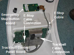 Note:
Note:If you are only replacing the e-stop button board, disconnect the e-stop cable and remove two screws. Install the new button.
Figure 7. Trackball Connector 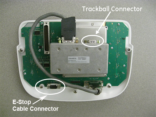
To install the new trackball control panel, follow Step 2 through Step 4 in reverse order.Notice Figure 8. EMO Reset on PDU 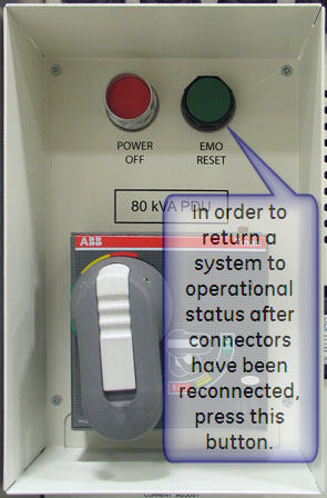
Replacing Standard Control Panels
Procedure
- The three control panels can be removed independently.
Figure 9. Location of Control Panels 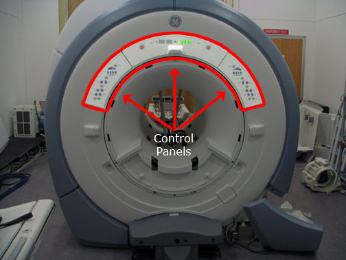
- Note:These panels are secured with poppers, but have hidden cables attached to each of them. Pull the control panels away from the cover, being careful not to pull the cables out.
The PDU must be powered down completely to prevent damage to system electronics.
Figure 10. Removing Control Panels 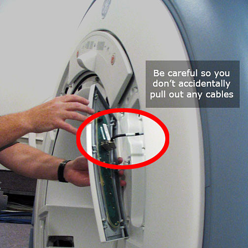
- After the panels are free from the enclosure, detach all the
cables from each control panel.
Figure 11. Connection Locations 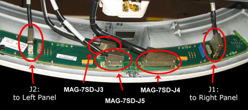
- To replace the control panels, reverse the above steps.
Figure 12. EMO Reset on PDU