
- Discovery MR750 3.0T System Service Methods
- 5690009-2EN Revision 4
- 00000018WIA302DAE20GYZ
- id_131065226.1
- Nov 22, 2021 2:15:38 PM
Laser light alignment
Prerequisites
| Required persons | Preliminary requirements | Procedure | Finalization |
|---|---|---|---|
| 1 | Not Applicable | 10 minutes | Not Applicable |
| Item | Quantity | Effectivity | Part number | Manufacturer |
|---|---|---|---|---|
| Non-Ferrous Allen Wrench Set | 1 | - |
| - |
| Non-Ferrous Flat Blade Screwdriver | 1 | - |
| - |
Procedure
- Check for proper alignment. The axial light should align with
the joints of the bridge endcap and bridge on each side of the bridge
and the sagittal light should align with the middle of the LPCA and
the middle of the table. If alignment is correct, you are done with
this procedure. Otherwise, continue with the steps that follow.
Figure 1. Proper alignment 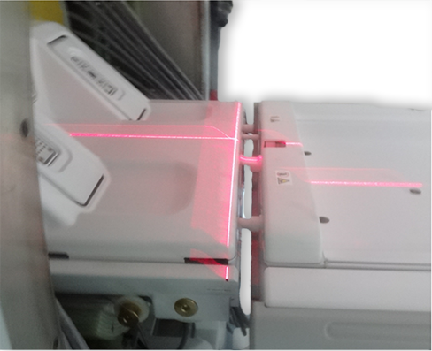
- Adjust the alignment via the joystick so that the axial light
(x-axis) is aligned to the bridge and endcap joints on both sides
of the bridge and the sagittal light (z-axis) is centered down the
middle of the bridge. See Figure 1 for proper alignment.Note: There is only one joystick to adjust the laser light.
Figure 2. Adjusting laser lights with single joystick 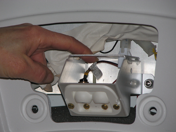
Finalization
- Complete DQA Calibration to calibrate isocenter by following the instructions in Troubleshooting the Daily Quality Assurance (DQA) II tool.
- If this is an adjustment and no further calibrations are needed, then complete a SAVEINFO to save current system calibrations.