• Discovery MR750 3.0T System Service Methods
  • 5690009-2EN Revision 4
  • Object ID: 00000018WIA30348E20GYZ
  • Topic ID: id_13107512 Version: 3.1
  • Date: Oct 11, 2021 8:47:14 PM

High Order Shim Functional Check

Prerequisites

Table 1. Personnel requirements
Required personsPreliminary requirementsProcedureFinalization
1Not Applicable30 minutesNot Applicable
Table 2. Tools and test equipment
ItemQuantityEffectivityPart numberManufacturer
Use applicable Head TLT Sphere, Silicon1-

-

-
Use applicable Head TLT Sphere Holder1-

-

-
Use applicable Body TLT Sphere, Silicon1-

-

-
Table 3. Safety

About this task

This procedure provides a qualitative method of testing the reference maps generated to insure basic functionality. Run the process on each of the reference maps generated. The process to functional check each Field Reference Map is:

  • Set up the phantom and select High Order Shim Series

  • Run back-to-back shim scans until the shim converges

  • Offset a shim channel and run another shim iteration

  • Confirm re-convergence of the shim channel offset

  • Repeat for all other shim volumes

Topic ID: id_SL1833635-1044976

Setup Scan Software

Procedure

  1. Note:

    This procedure should be run for 48 cm field of view (FOV) on the body coil, 28 cm FOV on the body coil, and 24 cm FOV on the head coil.

    Click New Pt.
    1. Patient ID: geservice.
    2. Weight: 111 lbs.
  2. Click Show All Protocols.
  3. Click GE and then Other protocols.
  4. Select "hos GE" and the series that corresponds to the FOV being tested, either 48 cm, 28 cm, or 24 cm.
  5. Click Accept.
Topic ID: id_SL1833643-1044976

Begin Scan

Procedure

  1. Place the correct phantom in the coil to be tested.
    1. Note:

      3.0T phantoms have pink solution. 1.5T phantoms have light green solution.

      For the 48 cm FOV Field Map: Set up the body TLT sphere phantom on the patient cradle. See Figure 1.
    2. For the 28 cm FOV Field Map: Set up the body TLT sphere phantom on the patient cradle. See Figure 1.
    3. For the 24 cm FOV Field Map: Place the head TLT phantom on the patient cradle. See Figure 2.
  2. Landmark on the appropriate location.
  3. Click Save and Start Exam, Save Rx, Scan. After the scan stops, the Shim User Interface appears.
  4. Position the ROI (use an oval shape) within the center of the spherical phantom image covering approximately 80% of the volume in all three planes. To move the ROI, click and drag inside the ROI. To change the size of the ROI, click and drag outside the ROI.
  5. Click Advanced, then Calculate Shim. The Advanced screen appears (Figure 4) that contains the specific shim information for each shim channel. See Figure 3 and Figure 4.
  6. Record data in Table 1, 2, or 3. 1849945.pdf
  7. If the Advanced Shim User Interface screen is open, click Download. Then in the Basic Shim User Interface screen (Figure 5) click [Quit].
  8. Click Scan again. When the pop up appears, select Add images to same series. Do not pre-scan between iterations.
  9. Repeat Step 1 through Step 8 for remaining reference maps. Test all reference maps for a system.
    Note:

    Run this procedure for 48 cm FOV on the body coil, 28 cm FOV on the body coil, 24 cm FOV on the head coil.

Topic ID: id_SL1833648-1044976

Achieving Convergence

Procedure

  1. Convergence is achieved when one of the following two conditions is met:
    1. The difference in Current RMS between two consecutive runs is less than 1 Hz (see Figure 3).
    2. The Advanced Interface (Figure 4) is asking for less than 30 mA (0.03 A) of Shim Current Delta.
      Note:

      The screen displays the Current RMS and Predicted RMS shim values shown on the basic screen to compare to the next iteration. Look at the Shim current deltas for each High Order Shim Channel. Convergence for these shim channels is defined as asking for less than 30 mA (0.03 A) of current change. The user interface displays units in amps.

  2. After convergence is achieved, the following steps are repeated for each channel until all shim channels are functionally tested. Only test one reference map/setup.
    1. Go to the Advanced screen and disable all channels except for the one to be tested by clicking on the button next to each channel. This process starts testing the ZY channel. Refer to Shim Channel Sequence and Delta Shim Current Data: 1849945.pdf for the sequence for the remaining channels.
    2. Enter a 100 mA offset by typing 0.1 in the current delta field for the channel being tested and select Done from the basic user screen to download and exit the interface.
    3. Click Scan to run the shim scan with the current offset. The user interface appears at the end of the scan.
    4. Click Advanced to open the Advanced screen again. Make sure only the ZY channel is enabled. You may need to deselect the other channels again. Channels stay disabled if they are deselected before using Calculate Shim but not after.
    5. Click Calculate Shim and look at the change requested for the ZY channel. The requested current change should be opposite in polarity from the offset entered in Step 2.b and should be about 70 mA in amplitude signifying at least a 70% requested correction of the shim offset. Usually for most channels you see much better than this. Record the delta current requested in the supplied data sheets: 1849945.pdf.
    6. Click Done to download the current delta and exit the interface.
    7. Click Scan and repeat Step 2.a through Step 2.f until at least 90% of the shim offset entered in Step 1 is recovered. Add the delta currents from each iteration and record them in the data sheets 1849945.pdf. The total recovered current should be between 0.090 and 0.100 amps See the example in the last row of the table.
      Note:

      Less than three iterations should be required, with one to two iterations typical. Delta currents < 40 mA on the first iteration or delta current that change polarity indicate a shim channel problem of either a dead channel or possibly an unstable shim output. This assumes the system passes the system performance test (SPT) stability and is clean of image artifacts.

    8. Repeat the substeps above for each of the other high order shim volumes.

    The following illustrations show the setup.

    Figure 1. Setup for 48 cm and 28 cm Field Map - Body TLT Sphere on Pads
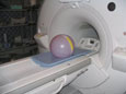
    Figure 2. Setup for 24 cm FOV Field Map - Head TLT Sphere in Head Coil
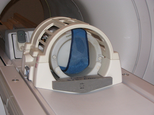
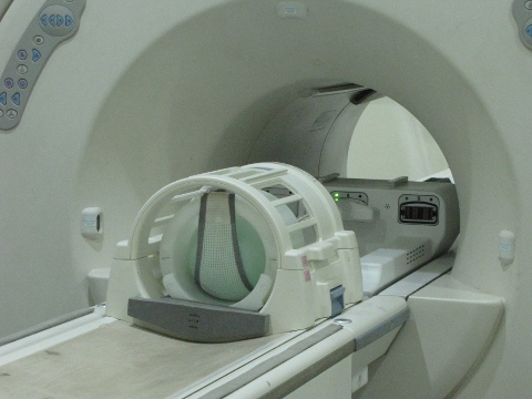
    Figure 3. Basic Shim User Interface after Clicking [Calculate Shim]
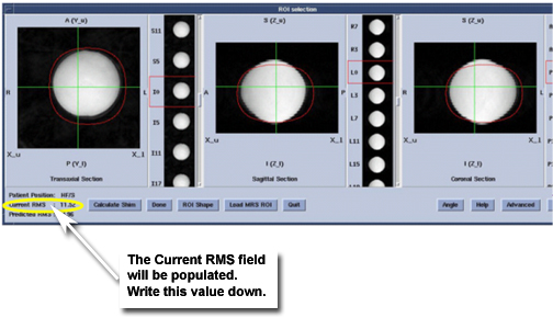
    Figure 4. Advanced Shim User Interface
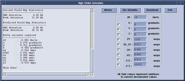
    Figure 5. Basic Shim User Interface
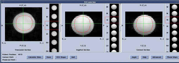
Topic ID: id_14965811

Finalization

Procedure

  1. Perform a Check Scan to ensure the scanner is ready for patient scanning.
  2. Put away any phantoms or tools used.