
- Discovery MR750 3.0T System Service Methods
- 5690009-2EN Revision 4
- 00000018WIA303BCE20GYZ
- id_131069462.0
- Feb 22, 2021 1:46:59 AM
HD 8-Channel CTL Coil Setup for MCQA Test
Prerequisites
| Required persons | Preliminary requirements | Procedure | Finalization |
|---|---|---|---|
| 1 | Not Applicable | 15 minutes | Not Applicable |
| Item | Quantity | Effectivity | Part number | Manufacturer |
|---|---|---|---|---|
| Phantom Kit, CTL Coil, 3.0T, CT Section | 1 | Legacy Phantom Set |
2381682-9 | - |
| Phantom Kit, CTL Coil, 3.0T, TL Section | 2 | Legacy Phantom Set |
2381682-10 | - |
| TL Unified Phantom, SiOil | 2 | Unified Phantom Set |
5343347-2 | - |
| Large Cylindrical Unified phantom, SiOil | 1 | Unified Phantom Set |
5342679-2 | - |
| Condition | Reference | Effectivity |
|---|---|---|
|
Coil configurations must be automatically installed in the system only for DVMR. The following coil configuration names are required to be present: | - | - |
About this task
This procedure will set up for the automated MCQA test using the 3.0T HD 8-Channel CTL array by GE (M3335LM).
Note:
Coils do not ship with phantoms. Phantoms come in a unified phantom set with the MR system.
Legacy Phantom Setup
Unified Phantom Setup
Procedure
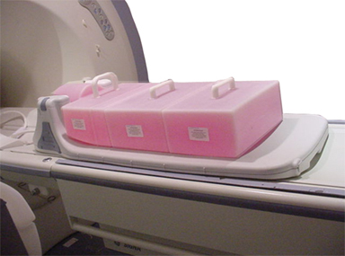
- Note:Place the coil on the patient table and latch it to the table as shown in Figure 4.
Connect the coil to the system as shown in Step 1.
Figure 4. Positioning the Coil 
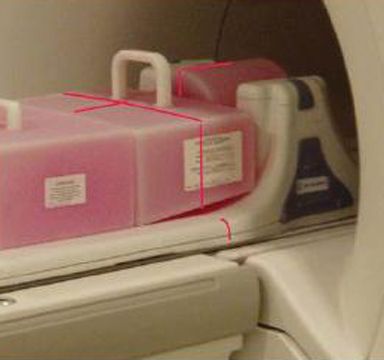
- Place the TL unified phantoms on the center of the TL section
of the coil as shown in Figure 5.
Figure 5. Aligning Phantom in S/I 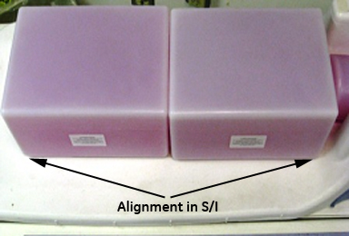
- Align the phantoms to the center in S/I and R/L directions as
shown Figure 5 and Figure 6.
Figure 6. Aligning Phantom in R/L 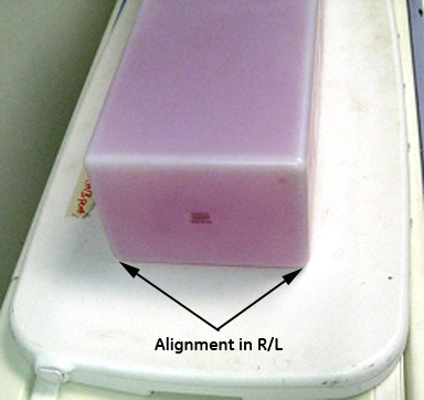
- Place the large cylindrical unified phantom on the CT section
as shown in Figure 7.
Figure 7. Positioning Phantom on CT Section 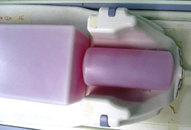
- Adjust the large cylindrical unified phantom such that it is
in complete contact with the TL unified phantom as shown in Figure 8.
Figure 8. Large Cylindrical Phantom in Complete Contact with TL Unified Phantom 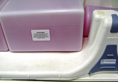
- Adjust TL unified phantoms such that both the phantoms are in
complete contact with each other as shown in Figure 9.
Figure 9. TL Unified Phantoms in Complete Contact with Each Other 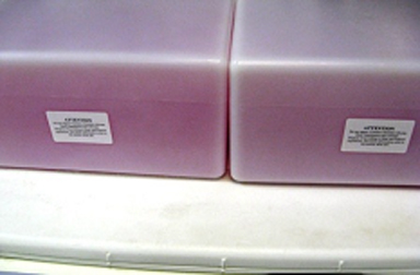
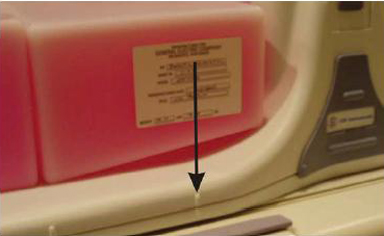
- Landmark the coil on the mark as shown in Figure 10. Advance to
scan.
Figure 10. Landmarking the Coil 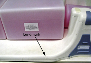
Finalization
Finalization
No finalization steps.