• Discovery MR750 3.0T System Service Methods
  • 5690009-2EN Revision 4
  • Object ID: 00000018WIA30FACE20GYZ
  • Topic ID: id_13106948 Version: 2.0
  • Date: Feb 22, 2021 1:46:58 AM

HD 8-Channel CTL Coil FRUs and Replacements

Prerequisites

Table 1. Personnel requirements
Required personsPreliminary requirementsProcedureFinalization
1Not Applicable30 minutesNot Applicable
Table 2. Tools and test equipment
ItemQuantityEffectivityPart numberManufacturer
Standard Tool Kit1---
Table 3. Replacement parts
ItemQuantityEffectivityPart numberManufacturer
GE 3T HD 8-Channel CTL FRU Cable1-

2417542

-

About this task

This document contains the cable replacement procedure for the 3T HD 8-Channel CTL Coil (GE/USAI catalog M3335LM). The field replaceable units and additional accessories for the 3T HD 8-Channel CTL Coil are listed in this document.

Topic ID: id_SL1985050-619549

Cable Removal

Procedure

  1. Remove coil bottom cover by removing all screws around the perimeter and down the center of the base.
  2. Remove the cable clamp (w/ 4 screws) that holds down the cable assembly (see Figure 1).
    Figure 1. Cable Assembly and the Interface Board
  3. Disconnect the SMB plugs (CH1-CH8) and DC plug on the cable end from the interface boards.
  4. Remove the old cable assembly. See Figure 2.
    Figure 2. CTL Coil Cable Assembly
Topic ID: id_SL1985055-619549

Cable Replacement

Procedure

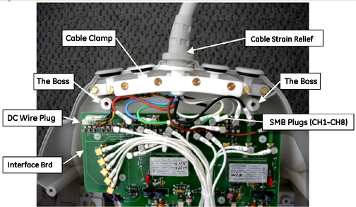
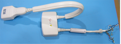
  1. Attach the new cable assembly (see Figure 2) to the coil and make sure the cable strain relief matches the notch of the former (see Figure 3). The side with Do Not Loop label of the in-cable box should face down (see Figure 3). If it does not face down, rotate the strain relief. Make sure that the cable clamp holds the cable jacket, and then tighten the cable clamp with the four screws.
    Figure 3. Cable Assembly Installation
  2. Connect all eight SMB plugs (CH1-CH8) and the DC Plug to the corresponding receptacles on the interface board. The receptacles are marked CH1-8 to correspond with the labels on the cables. Do not route RF cables and DC wires above the bosses shown in Figure 1; otherwise, the corresponding bosses on the bottom cover will squeeze the cables and DC wires when the bottom cover is closed.
Topic ID: id_SL1985057-619549

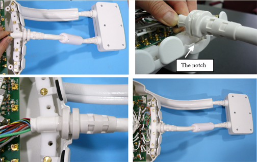
Field Replaceable Units and Additional Accessories

Procedure

  1. Refer to Table 4 for the 3T HD 8-Channel CTL Coil FRUs.
    Table 4. Field Replaceable Units
    Description GE Part #
    GE 3.0T HD 8-Channel CTL Array Coil2417540
    GE 3.0T HD 8-Channel CTL Array Cable2417542
    Legacy 3T 8-Channel CTL Phantom CT Section2381682-9
    Legacy 3T 8-Channel CTL Phantom TL Section2381682-10
    TL Unified Phantom5343347-2
    Large Cylindrical Unified Phantom5342679-2
  2. Refer to Table 5 for the 3T HD 8-Channel CTL Coil additional accessories.
    Table 5. Additional Accessories (Not FRU's)
    Description GE Part #
    Patient Comfort Pad2417543
    Ear Pad Set2414538
    Disposable Ear Pad Covers2380634-8
Topic ID: id_14963855

What to do next

Finalization

No finalization steps.