- Discovery MR750 3.0T System Service Methods
- 5690009-2EN Revision 4
- 00000018WIA30F4A030GYZ
- id_123732821.9
- Dec 20, 2021 3:35:05 PM
Troubleshooting Touch-and-Go (TnG)
Touch-and-Go (TnG) is an optional feature on DV systems. Touch-and-Go (TnG) provides landmarking push buttons on each side of the patient table.
| Notice | |
|---|---|
Theory of operation
Along the sides of the table, there are three electrically resistive strips in series per side. These strips are contained in the TnG assemblies, which consist of the resistive strips and brackets that hold them in place.
| Description | Quantity |
| Left Front TnG Assembly | 1 |
| Right Front TnG Assembly | 1 |
| Left Arm Board (Center) TnG Assembly | 1 |
| Right Arm Board (Center) TnG Assembly | 1 |
| Left Rear TnG Assembly | 1 |
| Right Rear TnG Assembly | 1 |
When a TnG button is pressed, the location on the resistive strip is read by the SRI4 using a voltage divider circuit based on the resistive value of the button. The SRI4 then converts this voltage to a digital signal using an A/D converter. There is a delta constant between the alignment light and the first TnG strip. This constant, along with the TnG button signal, is added to the value from the DQA calibration to get the correct advance to scan value.
Troubleshooting
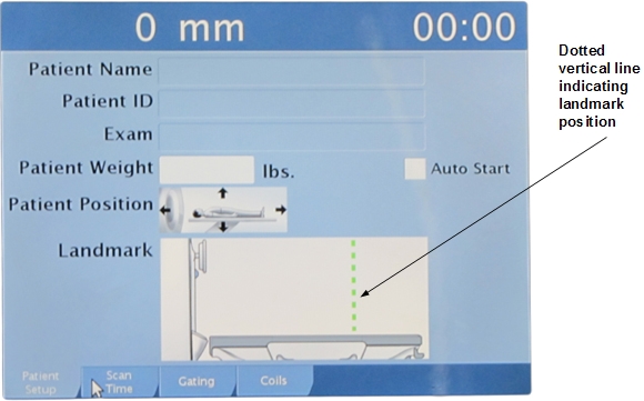
Testing Touch-and-Go (TnG)
- Bring the cradle to the home position.
- Select the Patient Setup tab on the IRD.
- Press a TnG button, and verify that a dotted vertical line appears at the approximate position where you pressed the button.
- Press and hold the Advance to Scan button (on the operator panel) until the cradle moves into the bore approximately 18 inches. (The amount of time that you need to hold the button depends on which TnG button you pressed.)
- Release the Advance to Scan button. The cradle should continue moving into the bore until it is at the landmarked position.
Touch-and-Go (TnG) diagnostics
The TnG Diagnostic is found on the SRI functional diagnostic menu.
When a TnG strip is pressed, the diagnostics page displays the ADC value read.
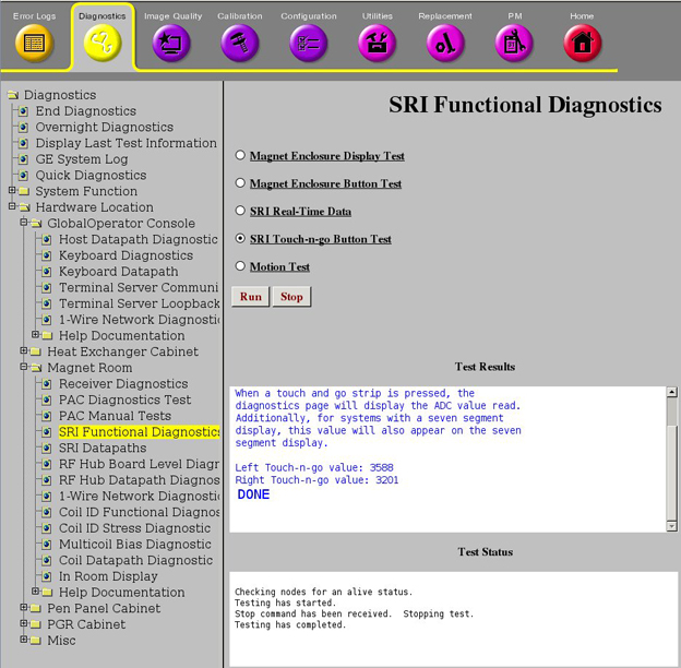
The following table shows an example of the ADC values you may see during the diagnostic.
| Right TnG value: 776 | This value is TnG button pressed near FRONT of table, and value is read again when button is released. |
| Right TnG value: 3196 | |
| Left TnG value: 1214 | This value is TnG button pressed near MIDDLE of table, and value is read again when button is released. |
| Left TnG value: 3187 |
The ADC value should return to its original value when the button is released. In the example above, the left TnG value should return to 3187, and the right TnG value should return to 3196.
Touch-and-Go (TnG) measurements
The following illustration shows a block diagram for TnG.
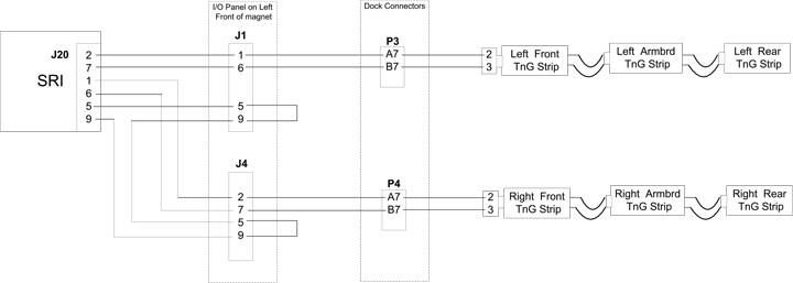
| Pin | Direction | Signal Name | Description |
|---|---|---|---|
| 1 | Input | LNDMRK_LEFT | Table left side landmark |
| 2 | Input | LNDMRK_RIGHT | Table right side landmark |
| 3 | NC | No connect | |
| 4 | Output | GND | GND |
| 5 | Output | GND | GND for landmark cable detect |
| 6 | Input | LNDMRK_LEFT_RTN | Table left side landmark return |
| 7 | Input | LNDMRK_RIGHT_RTN | Table right side landmark return |
| 8 | NC | No connect | |
| 9 | Input | LNDMRK_CBL_PRES_N | Landmark cable detect |
Isolating table signals
To isolate table signals, it is best to measure the resistance between A7 and B7 on both the P3 and P4 front table connectors.
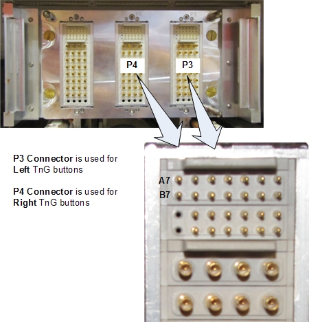
| Description | Resistance* |
|---|---|
| NO TnG button(s) pressed | 8.2K Ω |
| Front of first TnG strip | 315 Ω |
| Rear of first TnG strip | 600 Ω |
| Front of second TnG strip | 630 Ω |
| Rear of second TnG strip | 1.7K Ω |
| Front of third TnG strip | 1.77K Ω |
| Rear of third TnG strip | 3.14K Ω |
| * Values are approximate. Use only as a reference. | |
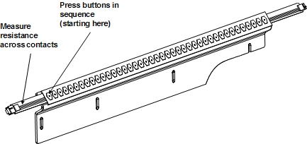
Isolating TnG strip signals
See Touch and Go Strip and Side Bumper Replacement for information about removing the TnG assemblies.
See Side Dock and Bumper Cables Replacement for information about replacing the TnG wiring harness.
The following illustration shows a schematic of the TnG strips.
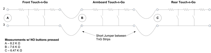
| This signal: | Should be: |
| Jumper cables | Jumper conductors should have continuity. |
| Front TnG assembly | Removed from the table, the front TnG assembly should have an open connection across its contacts. When you press the first button on the assembly, the resistance should be approximately 15 Ω. When you press the second button, the resistance should stay the same. When you press the third button, the resistance should increase by 15 Ω. This pattern will repeat as you press the buttons. The resistance increases by 15 Ω with every other button you press. |
| Arm board (center) TnG assembly | Removed from the table, the arm board TnG assembly should have an open connection across its contacts. When you press the first button on the assembly, the resistance should be approximately 30 Ω. When you press the next button, the resistance should remain the same. When you press the third button, the resistance should increase by 30 Ω. This pattern will repeat as you press the buttons. The resistance increases by 30 Ω with every other button you press. |
| Rear TnG assembly | Removed from the table, the rear TnG assembly should have a resistance of approximately 6.50 KΩ across its contacts. When you press the first button on the assembly, the resistance should be approximately 65 Ω. When you press the second button, the resistance should stay the same. When you press the third button, the resistance should increase by 65 Ω. This pattern will repeat as you press the buttons. The resistance increases by 65 Ω with every other button you press. |
The next illustration shows an example of a TnG assembly and the buttons to press.