- Discovery MR750 3.0T System Service Methods
- 5690009-2EN Revision 4
- 00000018WIA30F4A650GYZ
- id_20249112.0
- Mar 23, 2020 2:40:32 PM
UPM - MNS Troubleshooting and Theory
UPM - MNS Troubleshooting
- Check all cabling to the UPM boards to make sure that they are properly cabled.
- Repeat the UPM functional test (MNS).
- Cycle power to the UPM chassis.
- Reset TPS.
- Repeat the UPM functional test (MNS).
Solution 3: Reboot the system. Repeat the UPM functional test (MNS).
- Remove power from the UPM.
- Reseat the processor module.
- Restore power to the UPM.
- Reset TPS.
- Repeat the UPM functional test (MNS).
- Remove power from the UPM.
- Reseat the MNS detector boards.
- Restore power to the UPM.
- Reset TPS.
- Repeat the UPM functional test (MNS).
- Remove power from the UPM.
- Replace the processor module.
- Restore power to the UPM.
- Reset TPS.
- Repeat the UPM functional test (MNS).
- Remove power from the UPM.
- Replace both detector boards.
- Restore power to the UPM.
- Reset TPS.
- Repeat the UPM functional test (MNS).
For additional troubleshooting information, see Universal Power Monitor (UPM) troubleshooting.
UPM - MNS Theory
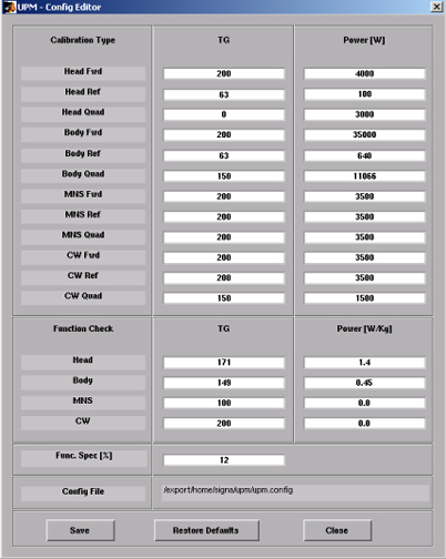
The UPM calibration parameters found in the UPM calibration file (/export/home/signa/tools/upm.config) are used in the calibration/functional check program. The program code sets the digital attenuators in the UPM based on the results of the tests run, and a comparison to these UPM calibration parameters. This calibration file is accessible from within the UPM calibration tool from the File menu, Edit Config option. These values can be edited and saved during troubleshooting to help understand where the power monitor is tripping (if at all). Before changing any parameters, make sure to select and run the Bkup UPM Cal option. This lets you return to the default values at any time. The UPM calibration file shown in Figure 1 contains the default configuration values for all of the UPM parameters. This screen is just for reference, because the content and values are different based on the system type and calibration results. Use Restore Defaults on the config file editor interface to return to known default values. The final UPM digital attenuator values are written to the UPM calibration configuration files (for example, Upm1Cal.cfg) located in the w/config directory.
- The format of Upm1Cal.cfg and Upm2Cal.cfg example is as follows:
- 85 Head FORWARD Power, attenuator setting in HEX
- 9f Head REFLECTED Power, attenuator setting in HEX
- 0 Head Quad Hybrid Reflected Power, attenuator setting in HEX (currently not used)
- 8d Body FORWARD Power, attenuator setting in HEX
- 8e Body REFLECTED Power, attenuator setting in HEX
- 9d Body Quad Hybrid Reflected Power, attenuator setting in HEX
- 93 MNS FORWARD Power, attenuator setting in HEX
- 83 MNS REFLECTED Power, attenuator setting in HEX
- 0 MNS Quad Hybrid Reflected Power, attenuator setting in HEX (currently not used)
- 0 CW FORWARD Power, attenuator setting in HEX (currently not used)
- 0 CW REFLECTED Power, attenuator setting in HEX (currently not used)
- 0 CW Quad Hybrid Reflected Power, attenuator setting in HEX (currently not used)
- Any changes to these values are temporary and can be restored by clicking Restore Defaults.
Figure 1. UPM Config Editor