
- Discovery MR750w and SIGNA™ Architect T 3.0T System Service Methods
- 5690002-2EN Revision 4
- 00000018WIA30D1AE20GYZ
- id_131075232.2
- Jul 6, 2019 12:03:29 AM
Heat Exchanger Theory
Contents
Introduction
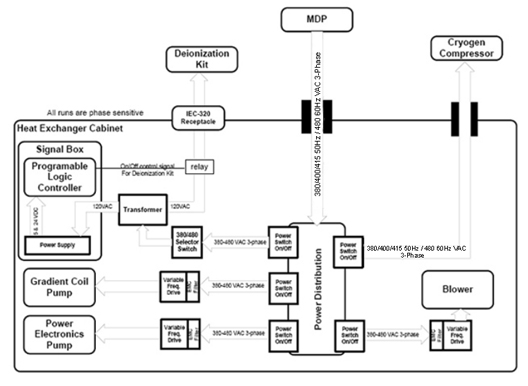
This document describes the function of the Heat Exchanger Cabinet (HEC), GE P/N 5161931. Fundamentally, the cooling cabinet provides a way for the gradient subsystem to exchange heat from the secondary coolant running through the power electronics and gradient coil to the primary facility coolant.
Facility (customer) coolant is provided to the HEC. Dual-loop, liquid-to-liquid heat exchangers are used to circulate DVMR coolant through the power, gradient and RF (PGR) cabinet and gradient coil, critical components of an MR system. The heat exchanger module isolates the deionized water closed-loop coolant from the facility coolant so that these do not come into contact and mix. The HEC must control and monitor control parameters and interface to the MR system. A small portion of customer coolant is provided to the cryocooler compressor. The HEC also houses a chilled air blower and provides cryocooler compressor temperature and volumetric flow signals to the magnet monitor.
Additional information for the HEC can be found in the vendor manual and in the Interactive Block Diagrams.
Electrical Power
Overview
The HEC receives power from the main disconnect panel (MDP), which is routed and rectified inside the HEC. The deionization kit and cryocooler compressor receive electrical power from the cooling cabinet.
Main Electrical Power
Overview
The HEC accepts a three-phase, solidly grounded WYE with ground (four-wire system) at 380/400/415 VAC, 50 ±3 Hz or 480 VAC, 60 ±3 Hz from the MR system MDP. It requires no more than 20 kVA maximum continuous power and 20 kVA peak power. The HEC has a maximum breaker rating of 50 amps, and is equipped with a ground stud. All electrical connections are routed through the top of the cabinet.
Power Switch Labeling
Power switches are labeled inside the power box as follows:
-
Power electronics pump: PPMP CB
-
Gradient coil pump: GPMP CB
-
Controller/signal box: PWR CB
-
Cryo compressor: CRY CB
-
Chiller air blower: BLW CB
Pumps
The pumps are driven by variable frequency drives (VFD) located inside the HEC to provide the same capability, given the voltage and frequency requirements listed in Overview. The pumps receive power from within the HEC, are ramped at startup, and are protected against phase reversal. The pump motor is rated between 40 and 70 Hz for possible VFD operation. VFD line noise is filtered inside the cabinet, and does not enter the line or get emitted outside of the cabinet.
Beginning in early 2012, HEC cabinets began shipping with pumps from the manufacturer, Price. The pump type must be exactly matched with the correct VFD chip or there will be either high pressure or low flows, risking equipment damage and/or system errors. Price pumps can be identified by an irregularly shaped pump face. The older Ebara pumps have a circular pump face. Ebara VFD chips do not have any markings on them; the Price chips are identified with a “P”.
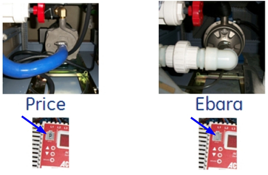
Both pumps provide equivalent flow and pressure to the system when operated at the correct, respective speed (achieved via proper VFD chip usage).
The displayed values in Table 1 and Table 2 apply when HEC is in a scan-ready state and not in low power mode.
| Pump type | EBARA | PRICE |
| Displayed value (VFD GPMP) | 50 +/-1 | 61 +/-1 |
| Pump type | EBARA | PRICE | ||
| RF amplifier type (water cooled has red and blue hoses hooked up to the RF amp; air cooled does not have hoses.) | Liquid | Air | Liquid | Air |
| Displayed value (VFD PPMP) | 50 +/-1 | 43 +/-1 | 61 +/-1 | 53 +/-1 |
Cryocooler Compressor
The HEC routes incoming power to the cryocooler compressor. Power allocation for the cryocooler compressor is 9 kVA (12 amps nominal), and the maximum power consumption is 12 kVA. The power switch for the cryocooler compressor is at least 15 amps. The power cables are sized per GE Healthcare drawing 2188440-2.
The circuit breaker in the HEC is a manual power switch for the cryocooler compressor. The HEC does not automatically reset power to the cryocooler compressor. If the cryocooler compressor shuts down because of inadequate water flow, it may take a manual power cycle in the HEC to restart the cryocooler compressor once water flow is restarted.
Deionization Kit
The HEC provides 120 VAC (50 or 60 Hz) with a maximum of 5 amps to the deionization kit. Power to the deionization kit service outlet is turned on or off via the HEC controller. A standard NEMA 5-15P hospital grade receptacle (labeled DI KIT) is located on the top or front of the cabinet and provides a way to connect to the deionization kit.
Chilled Air Blower
The chilled air blower is driven by a VFD located inside the cabinet in order to provide the same capability, given the voltage and frequency requirements listed in Overview. The chilled air blower receives power from within the HEC, is ramped at startup and protected against phase reversal. It is rated for VFD operation. VFD line noise is filtered inside the cabinet, and does not enter the line or get emitted outside of the cabinet. The supplier is responsible for assisting GE Healthcare Engineering in resolving any EMC-related issues resulting from VFD operation.
Operation
The HEC has:
-
A low-power mode for long periods of MR system inactivity (for example, for night time operation) where the pumps and blower may operate at a lower frequency (speed). The low-power command comes from the MR host computer approximately 15 minutes after an exam is ended. After a new scan is prescribed, the HEC exits low-power mode.
-
An automatic restart function that allows the HEC pumps to restart when power is restored to the facility after a power outage without any action required from the operator.
Performance
Overview
Customer-Supplied Coolant
Coolant Characteristics and Quality
The customer is responsible for providing cooling water with up to 40% propylene glycol by volume for intake by the HEC. Coolant pH range, coolant quality, and filtration requirements are in the Pre-Installation Manual for the given MR system. Any deviation of temperature or pressure outside of limits is reported to the system message log.
Flow and Pressure
The HEC provides a means for isolating and draining the customer-supplied coolant contained within the cabinet. GE Healthcare specifies the type of thread, but does not specify any particular method or hose/piping type to connect the facility chiller supply/return to the HEC.
The customer is responsible for:
-
Continuously providing coolant to the HEC at a supply pressure not exceeding 6 bar (87 psi) measured at the inlet of the HEC.
-
Providing coolant supply connections to interface the customer’s piping and hoses to the 1.5 inch female NPT threads at the top of the HEC.
-
The HEC requires a specific range of incoming coolant flow and pressure from the site's chilled water supply or chiller based on the type of fluid used. The minimum and maximum specifications are listed in the Pre-Installation Manual for the given MR system. These minimum and maximum values were chosen to effectively perform cooling for the MR system and must be strictly adhered to.
Temperature
The HEC requires a specific range of incoming coolant temperature from the site's chilled water supply or chiller. The minimum and maximum allowable temperatures are listed in the Pre-Installation Manual for the given MR system. Differences may exist among systems. These minimum and maximum temperatures were chosen to effectively perform cooling for the MR system, and must be strictly adhered to.
Cabinet catalogs G6000EN and G6001EN allow different incoming coolant temperatures because they contain different hardware. See the illustrations below to determine which style HEC is installed. The HEC type selection is made in Guided Install. This matches the hardware with the proper code and operating parameters to allow the HEC to operate in the facility water temperature ranges specified in the Pre-Installation Manual.
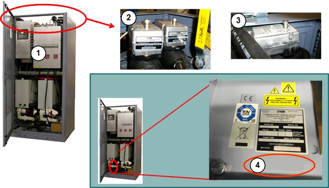
| 1 | HEC catalog number G6000EN | 3 | Chilled air mixing valve |
| 2 | GC/PE mixing valve | 4 | No G-catalog label |
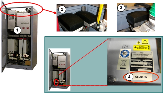
| 1 | HEC catalog number G6001EN | 3 | Chilled air mixing valve |
| 2 | GC/PE mixing valve | 4 | Catalog label G6001EN |
Because the incoming temperature of water is significantly colder than room temperature, condensation on the hoses and internal components in the HEC is a possibility. The facility lines in the HEC are insulated to minimize the amount of condensation collecting on the piping and dripping inside the HEC. The customer should provide insulation for their chilled water lines, valves, and flow meters if condensation collection becomes an issue.
Sensors
The HEC uses sensors to measure these characteristics of the customer-supplied coolant:
-
Supply and return pressures
-
Temperature
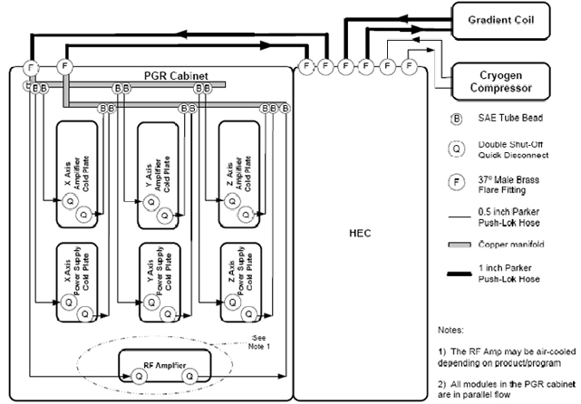
Coolant Distribution in PGR Cabinet
The illustration below shows the coolant distribution inside the PGR cabinet along with hose sizes and connectors.
Gradient Coil
Coolant Characteristics and Quality
The HEC circulates the coolant specified in GEHC document 5174313PSP through the gradient coil. The gradient coil coolant may come into contact with copper, brass, plastic, and stainless steel materials only. The gradient cooling loop does not use parts that may introduce ferrous particles into the coolant.
The coolant circulated through the gradient coil is specifically formulated for the MR system. It contains blue colorant and low levels of corrosion inhibitors and biocides. Additionally, the coolant is specifically maintained to be highly resistive, so leakage currents from the gradient coil do not create unsafe conditions elsewhere in the MR system. The coolant may be disposed of in any standard drain, because it does not contain high concentrations of hazardous chemicals.
Flow and Pressure
The HEC pumps water through the gradient coil at pressures below 6.0 bar. The programmable logic controller in the HEC uses the known pump speed and measured coolant pressure to derive a flow rate through the coil. The MR host computer contains setpoints for the pump speed as well as low-flow alarm limits in a configuration file specific to the given MR system and coil design.
Supply and return connections for the gradient coil are 1 inch, 37° (JIC) brass, male, flare fittings located at the top of the HEC. The supply connection on the gradient coil has a blue color indicator, and the return connection has a black color indicator. Supply and return gradient coil connections are electrically grounded to the cabinet, because the coolant is exposed to 660 amps ±1,650 volts inside the gradient coil.
Temperature
The gradient coil coolant supply temperature is set to 18 °C in a configuration file on the MR host computer. The HEC provides coolant to the gradient coil at a temperature within ±1 °C of the setpoint temperature. The desired gradient coil coolant supply temperature is communicated to the HEC via the method specified in Setpoint Control, System Configuration and Alarms.
The cooling capacity of the gradient coil cooling loop is at least 25 kW. The parameters that define the gradient coil temperature control loop are stored in a configuration file on the MR host computer and communicated to the controller via the method specified in Setpoint Control, System Configuration and Alarms.
If the temperature reaches 40 °C, the pump is shut off for safety reasons. If a pump is turning itself on and off and the temperature is >40 °C, see HEC Troubleshooting.
Sensors
Sensors in the HEC measure the following gradient coil coolant parameters:
-
Resistivity
-
Supply pressure
-
Supply temperature
The HEC also:
-
Measures or derives gradient coil volumetric flow.
-
Monitors two reservoir-level switches that turn on when gradient coil coolant volume levels reach Warning and Alarm levels. The pump automatically shuts off when the liquid level in the reservoir reaches the Alarm level.
Power Electronics Coolant
Coolant Characteristics and Quality
| Notice | |
|---|---|
The HEC circulates the coolant, specified in GE Healthcare document 5174313PSP, through the PGR cabinet. This coolant is specifically formulated for the MR system. It contains blue colorant and low levels of corrosion inhibitors and biocides. The coolant may be disposed of in any standard drain, because it does not contain high concentrations of hazardous chemicals.
Flow and Pressure
The HEC pumps liquid coolant through the PGR cabinet at pressures below 6.0 bar. The flow rate through the PGR cabinet is set via the pump speed, and communicated by the MR host computer. This pump speed and the subsequent flow rate may be different for each MR system, because some systems use a liquid-cooled RF amplifier in the PGR cabinet.
-
Flow rate is derived from the known pump speed and measured coolant pressure in the HEC.
-
Low-flow and high-flow Alarm setpoints are defined in a configuration file on the host computer, and post error messages when necessary.
The supply and return connections for the PGR cabinet are 1 inch, 37° (JIC) brass, male, flare fittings located at the top of the HEC. The supply connection on the PGR cabinet has a green color indicator, and the return connection has a red color indicator.
Temperature
The HEC provides coolant to the PGR cabinet at 30 °C. The temperature may automatically increase to 35 °C, based on the local dewpoint temperature inside the PGR cabinet, to minimize condensation. Relative humidity and ambient temperature inside the PGR cabinet are communicated to the HEC controller via the method specified in Setpoint Control, System Configuration and Alarms. The controller calculates the dewpoint temperature. The cooling capacity of the PGR cabinet cooling loop is at least 35 kW. Parameters that define the power electronics temperature control loop are stored in a configuration file on the MR host computer.
If the temperature reaches 40 °C, the pump is shut off for safety reasons. If a pump is turning itself on and off and the temperature is >40 °C, see HEC Troubleshooting.
Sensors
Sensors in the HEC measure the power electronics coolant pressure and temperature. The HEC measures or derives the power electronics coolant volumetric flow, and monitors two reservoir-level switches that turn on when the power electronics coolant volume levels reach Warning and Alarm levels. The pump automatically shuts off when the liquid level in the reservoir reaches the Alarm level.
Cryocooler Compressor
Coolant Characteristics and Quality
The cryocooler compressor uses a portion of the same customer-provided coolant to the HEC, and operates under the customer coolant characteristics specified in Customer-Supplied Coolant. Inside the HEC, a flow restrictor splits flow from the customer-supplied coolant to provide the cryocooler compressor with a relatively constant flow rate. Changes or reductions in flow rate may indicate:
-
Inadequate total flow coming from the customer-provided chiller into the HEC.
-
Cryocooler compressor filter, located at the top of the HEC, is clogged.
The filter is a FRU, but is also cleanable. The HEC provides a bypass to allow uninterrupted flow when changing this filter.
Flow and Pressure
The HEC allocates at least 7 L/min (1.8 gpm) of the customer-supplied coolant to the cryocooler compressor 24 hours per day, 7 days per week, 365 days per year to maximize proper uninterrupted magnet operation. Supply and return connections for the cryocooler compressor are 0.5 inch, 37° (JIC) brass, male, flare fittings located at the top of the HEC. The supply connection on the cryocooler compressor has a gray color indicator, and the return connection has a yellow color indicator.
Temperature
The cryocooler compressor uses a portion of the same customer-supplied coolant to the HEC, and operates under the customer-supplied water temperatures specified in Temperature.
Sensors
The volumetric flow of the coolant supplied to the cryocooler compressor is measured using a flow meter inside the HEC. The signal box in the HEC has a 9-pin, sub D connector that communicates cryocooler flow and coolant temperature to the magnet monitor. The pin outs of the connector are shown below.
| Pin | Function |
|---|---|
| 1 | Common |
| 2 | Common |
| 6 | Cryocooler compressor flow |
| 7 | Compressor temperature |
Chilled Air Blower
Air Flow and Quality
The HEC draws air from the scan room through a 3 inch, female NPT thread located on the top of the HEC. The scan room air is maintained by the customer within the environmental ranges as stated in the Pre-Installation Manual.
Flow and Pressure
The HEC is designed to supply adequate chilled air flow and pressure to maintain cooling in the RF body coil air space. This chilled air cools the RF body coil, and maintains bore temperatures within regulated limits. The MR host computer sounds an alarm based on the flow rate (measured inside the magnet bore with airflow sensors) and temperature (measured at the output of the HEC). The chilled air supply connection is a 3 inch, female NPT thread located on the top of the HEC. To reduce the risk of condensation, customer-provided coolant is not supplied to the liquid-to-air heat exchanger when the blower is off.
The value displayed on the HEC controller for airflow is a direct feed of the air velocity measured by the airflow sensors in the magnet bore. This value is communicated to the HEC via Ethernet. If the Ethernet cable is unplugged or upstream hardware is turned off (for example, SRI), this value is not updated.
Temperature
The chilled air supply temperature is specific to the MR system, and set via the MR host computer.
The HEC provides chilled air at a temperature within ±2 °C of the setpoint temperature.
-
Temperature excursions greater than +3 °C inhibit the current scan.
-
Temperature excursions greater than ±2 °C of the setpoint inhibit the next exam.
The parameters that define the chilled air temperature control loop are stored in a configuration file on the MR host computer, and communicated to the controller via the method specified in Setpoint Control, System Configuration and Alarms.
Sensors
The HEC measures the chilled air temperature before it leaves the cabinet.
PLC Controller
Introduction
The PLC controller is the “brain” of the HEC and its job is to:
-
Turn the pumps and blower on and off
-
Instruct the pumps and blower at what frequency to run
-
Maintain the gradient coil coolant, power electronics coolant, and RF chilled air temperatures at setpoint via PID control of the three-way mixing valves in the facility water piping
-
Monitor sensors and generate warnings or alarms from the MR host computer until instructed otherwise
The controller is connected to the SCP via Ethernet, and has a secondary serial connection between the controller and terminal server. During a TPS reset, the MR host computer updates the PLC code if necessary, and passes the setpoint and alarm variables that reside in a configuration file.
Configuration File
The cooling cabinet configuration file can be found in /w/config/cooling.cfg.
Setpoints
Setpoint parameters vary among MR systems and are shown below.
| Parameter | Meaning | Units |
| grad_coolant_flowrate | Pump frequency for gradient coil loop | Hz |
| grad_coolant_temp_setpoint | Coolant temperature delivered to gradient coil | 0.1° C |
| xgd_coolant_flowrate | Pump frequency for PGR cabinet | Hz |
| rf_air_flowrate | Blower frequency for chilled air supply | Hz |
| rf_air_temp_setpoint | Coolant temperature for chilled air supply | 0.1° C |
The power electronics supply temperature (formerly xgd_coolant_temp_setpoint) is derived from the XGD air temperature and humidity. The minimum temperature is 30 °C.
Alarms
PLC alarm parameters are shown below.
| Parameter | Meaning | Units |
| cust_coolant_temp_low_limit | Lower limit for facility supply temperature | 0.1° C |
| cust_coolant_temp_high_limit | Upper limit for facility supply temperature | 0.1° C |
| cust_coolant_press_low_limit | Lower limit for facility supply pressure | 0.1 bar |
| cust_coolant_press_high_limit | Upper limit for facility supply pressure | 0.1 bar |
| cust_coolant_press_diff_low_limit | Minimum pressure differential between facility supply and return pressures | 0.1 bar |
| cust_coolant_return_pr_low_limit | Lower limit for facility return pressure | 0.1 bar |
| cust_coolant_return_pr_high_limit | Upper limit for facility return pressure | 0.1 bar |
| grad_coolant_temp_low_limit | Lower limit for gradient coil supply temperature | 0.1° C |
| grad_coolant_temp_high_limit | Upper limit for gradient coil supply temperature | 0.1° C |
| grad_coolant_press_low_limit | Lower limit for gradient coil supply pressure | 0.1 bar |
| grad_coolant_press_high_limit | Upper limit for gradient coil supply pressure | 0.1 bar |
| grad_coolant_flowrate_low_limit | Lower limit for gradient coil flow rate | 0.1 L/min |
| grad_coolant_flowrate_high_limit | Upper limit for gradient coil flow rate | 0.1 L/min |
| grad_coolant_resist_low_alarm | Alarm for coolant resistivity on gradient coil loop | 0.1 MOhm-cm |
| xgd_coolant_temp_low_limit | Lower limit for power electronics supply temperature | 0.1° C |
| xgd_coolant_temp_high_limit | Upper limit for power electronics supply temperature | 0.1° C |
| xgd_coolant_press_low_limit | Lower limit for power electronics supply pressure | 0.1 bar |
| xgd_coolant_press_high_limit | Upper limit for power electronics supply pressure | 0.1 bar |
| xgd_coolant_flowrate_low_limit | Lower limit for power electronics flow rate | 0.1 L/min |
| xgd_coolant_flowrate_high_limit | Upper limit for power electronics flow rate | 0.1 L/min |
| rf_air_temp_low_limit | Lower limit for chilled air temperature | 0.1° C |
| rf_air_temp_upper_limit | Upper limit for chilled air temperature | 0.1° C |
| rf_air_velocity_low_limit | Lower limit flow rate for chilled air | cfm |
| rf_air_velocity_high_limit | Upper limit flow rate for chilled air | cfm |
| cryo_coolant_flowrate_low_limit | Lower limit for cryocooler compressor flow rate | 0.1 L/min |
| cryo_coolant_flowrate_high_limit | Upper limit for cryocooler compressor flow rate | 0.1 L/min |
| grad_coolant_resist_low_warning | Warning for coolant resistivity on gradient coil loop | 0.1 MOhm-cm |
Scan-Inhibiting Alarms
Alarms that inhibit scanning are listed below.
| Customer-Supplied Coolant Supply Temperature High Alarm |
| Customer-Supplied Coolant Supply Pressure Low Alarm |
| Gradient Coil Coolant Supply Temperature High Alarm |
| Gradient Coil Coolant Supply Pressure Low Alarm |
| Gradient Coil Coolant Supply Pressure High Alarm |
| Gradient Coil Coolant Supply Flow Rate Low Alarm |
| Gradient Coil Coolant Resistivity Low Alarm (inhibit new scans) |
| Gradient Coil Coolant Supply Reservoir Low Alarm (immediate stop) |
| Power Electronics Coolant Supply Temperature High Alarm |
| Power Electronics Coolant Supply Pressure Low Alarm |
| Power Electronics Coolant Supply Pressure High Alarm |
| Power Electronics Coolant Supply Flow Rate Low Alarm |
| Power Electronics Coolant Supply Reservoir Low Alarm (immediate stop) |
| RF Body Coil Chilled Air Temperature High Alarm |
| RF Body Coil Chilled Air Velocity Low Alarm |
| SCP-Cooling Ethernet Cabinet Failures for 5 seconds |
Controller Display
The controller display can:
-
Show real-time sensor information
-
Display setpoints and operating parameters
-
Operate the deionization kit
-
Set Ethernet address
Other than Ethernet address values, no settings or parameters are modifiable from the controller display.
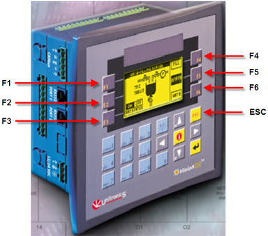
Navigation is performed using the function keys, F1 to F6. Press ESC to return to the previous page.
Information for individual screens is listed in the sections that follow.
Heat Exchanger (Main) Display
From the main HEC display, access the desired display by pressing the key next to the selection.
-
Monitor display (F3)
-
Deionization kit (F4)
-
Ethernet settings (F5)
-
Diagnostics (F6)
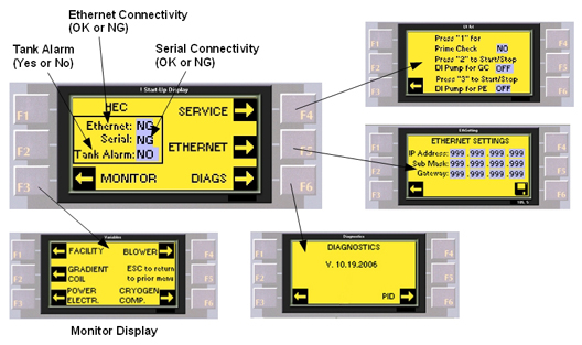
NG stands for No Good.
The HEC has both Ethernet and serial connections to obtain HEC status and sensor data as well as provide operating parameters. The Ethernet and serial cables are routed through the top of the HEC.
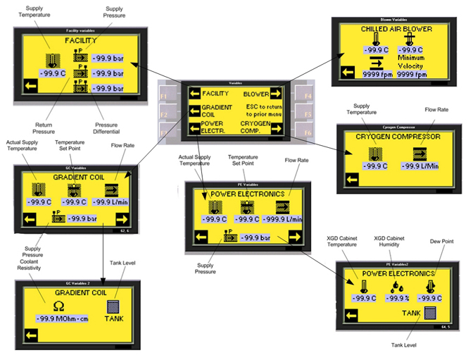
Monitor Display and Sub-Displays
From the monitor display, access the desired display by pressing the key next to the selection.
-
Facility (F1)
-
Gradient coil (F2)
-
Power electronics (F3)
-
Chilled air blower (F4)
-
Cryogen compressor (F6)
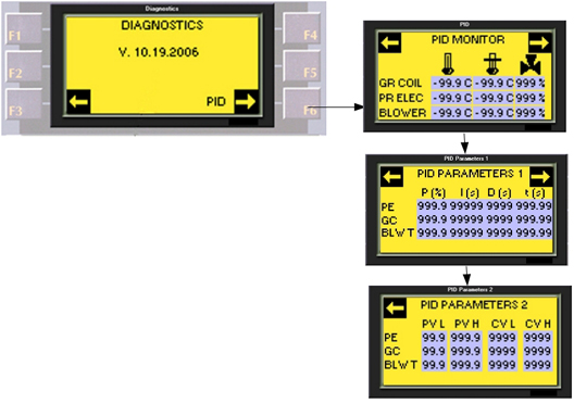
Diagnostic Display with Sub-Displays
From the diagnostic display, access the PID monitor display by pressing F6.
Setting PLC IP Address
The MR host computer automatically writes the required parameters for Ethernet communication with the PLC via the serial cable connecting the signal box to the MR system.
| Notice | |
|---|---|
-
Go to the PLC.
-
Press F5 to go the Ethernet screen.
Figure 12. HEC Main Screen 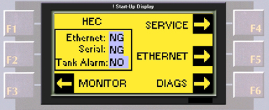
-
Make a note of the IP address. (To return to the main screen, press ESC.)
Note:If unable to navigate through the screens, make sure the system is not scanning, and reset the power to the cooling cabinet by flipping the left circuit breaker that is farthest left in the power box.
If the PLC does not display the Ethernet settings, follow the steps below after plugging the CAT5 Ethernet cable into the PLC:
-
-
Go to the PLC, and press F5 on the HEC Main screen.
Figure 13. Entering IP Address 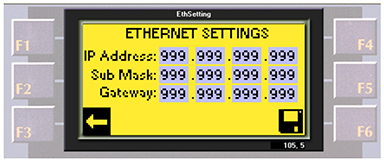
-
At the Ethernet Settings screen, type the appropriate numbers and press Enter after each entry. (Use the IP address noted above.)
Note:It may be necessary to press the button for a second longer so the cursor moves to the next slot.
-
Enter IP: 10.0.1.11.
-
Enter Sub Mask (subnet mask): 255.255.0.0.
-
Enter Gateway: 10.0.1.1.
-
-
Press F6 to save the network settings.
Note:After the settings are saved, the main screen displays. The Ethernet readout on the PLC displays OK instead of NG after the connection TPS reset is completed. If NG, there will be errors in the error log.
Figure 14. Ethernet Status 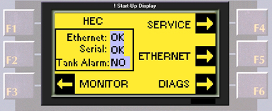
Starting and Stopping Pumps and Blower
| Notice | |
|---|---|
To toggle the pumps and blower on and off, do the following:
-
Blower: Press and hold the up arrow (^) and press F1.
-
Gradient coil pump: Press and hold the up arrow (^) and press F2.
-
Power electronics pump: Press and hold the up arrow (^) and press F3.
Communication and Alarms
Protection Devices
The HEC shuts down the appropriate pumps, and registers an alarm when the reservoir volumes fall below the specified shutoff (alarm) levels.
Setpoint Control, System Configuration and Alarms
Setpoint Parameters
The setpoint parameters listed in the tables below are stored in a configuration file on the MR host computer and communicated to the HEC controller.
| Parameter | Units |
| Gradient Coil Coolant Temperature Setpoint [°C] | 0.1° C |
| Gradient Coil Pump Speed [Hz] | Hz |
| Power Electronics Pump Speed [Hz] | Hz |
| Chilled Air Temperature Setpoint [°C] | 0.1° C |
| Default Chilled Air Blower Speed [Hz] | Hz |
| Requested Chilled Air Velocity measured at gradient coil | feet/min. |
| Parameter | Units |
| Gradient Coil Proportional Band | 0.1% |
| Gradient Coil Integral Time | sec |
| Gradient Coil Derivative Time | sec |
| Gradient Coil Sample Time | 10 msec |
| Gradient Coil process Value Lower Limit | 0.1 °C |
| Gradient Coil process Value Upper Limit | 0.1 °C |
| Gradient Coil Control Value Lower Limit | bits |
| Gradient Coil Control Value Upper Limit | bits |
| Parameter | Units |
| Power Electronics Proportional Band | 0.1% |
| Power Electronics Integral Time | second |
| Power Electronics Derivative Time | second |
| Power Electronics Sample Time | 10 msec |
| Power Electronics Process Value Lower Limit | 0.1 °C |
| Power Electronics Process Value Upper Limit | 0.1 °C |
| Power Electronics Control Value Lower Limit | bits |
| Power Electronics Control Value Upper Limit | bits |
| Parameter | Units |
| Chilled Air Temperature Proportional Band | 0.1% |
| Chilled Air Temperature Integral Time | sec |
| Chilled Air Temperature Derivative Time | sec |
| Chilled Air Temperature Sample Time | 10 msec |
| Chilled Air Temperature Process Value Lower Limit | 0.1 °C |
| Chilled Air Temperature Process Value Upper Limit | 0.1 °C |
| Chilled Air Temperature Control Value Lower Limit | bits |
| Chilled Air Temperature Control Value Upper Limit | bits |
HEC Humidity and Temperature
The information below is communicated to the HEC controller.
| Parameter | Units |
| PGR Cabinet Internal Relative Humidity | 0% |
| PGR Cabinet Internal Ambient Temperature | 0.1° C |
Warning/Alarm Levels
The warning/alarm levels shown in the tables below are stored on the MR host computer and communicated to the HEC controller.
| Parameter | Units |
| Customer Coolant Low Temperature Alarm | 0.1° C |
| Customer Coolant High Temperature Warning | 0.1° C |
| Customer Coolant High Temperature Alarm | 0.1° C |
| Customer Coolant Low Supply Pressure Alarm | 0.1 bar |
| Customer Coolant High Supply Pressure Alarm | 0.1 bar |
| Customer Coolant Low Return Pressure Alarm | 0.1 bar |
| Customer Coolant High Return Pressure Alarm | 0.1 bar |
| Customer Coolant Low Pressure Difference Alarm | 0.1 bar |
| Customer Coolant Reversed Flow Alarm | ----- |
| Parameter | Units |
| Gradient Coil Coolant Low Temperature Alarm | 0.1° C |
| Gradient Coil Coolant High Temperature Alarm | 0.1° C |
| Gradient Coil Coolant Low Supply Pressure Alarm | 0.1 bar |
| Gradient Coil Coolant High Supply Pressure Alarm | 0.1 bar |
| Gradient Coil Coolant Low Flow Alarm | L/min |
| Gradient Coil Coolant Low Flow Warning | L/min |
| Gradient Coil Coolant High Flow Alarm | L/min |
| Gradient Coil Low Resistivity Warning | kOhm-cm |
| Gradient Coil Low Resistivity Alarm | kOhm-cm |
| Gradient Coil Reservoir Low Warning | ----- |
| Gradient Coil Reservoir Low Alarm | ----- |
| Parameter | Units |
| Power Electronics Coolant Low Temperature Alarm | 0.1° C |
| Power Electronics Coolant High Temperature Alarm | 0.1° C |
| Power Electronics Coolant Temperature Change High Alarm | 0.1° C |
| Power Electronics Coolant Low Supply Pressure Alarm | 0.1 bar |
| Power Electronics Coolant High Supply Pressure Alarm | 0.1 bar |
| Power Electronics Coolant Low Flow Alarm | L/min |
| Power Electronics Coolant Low Flow Warning | L/min |
| Power Electronics Coolant High Flow Alarm | L/min |
| Power Electronics Coolant Low Warning | ----- |
| Power electronics reservoir low alarm | ----- |
| Parameter | Units |
| Chilled Air Low Temperature Alarm | 0.1° C |
| Chilled Air High Temperature Warning | 0.1° C |
| Chilled Air High Temperature Alarm | 0.1° C |
| Parameter | Units |
| Cryocooler Compressor Low Flow Alarm | L/min |
| Cryocooler Compressor High Flow Alarm | L/min |
Heat Exchanger Cabinet Version
The HEC provides configuration information through digital input memory addresses I9 and I10 as shown below.
| 5161931 PSP | Cabinet Version | I9 | I10 |
| Rev 1 | Generation 2 | 0 | 0 |
| Rev 2 to present revision | Generation 3 |
Sensor Information for Host Computer
The HEC provides the sensor information, which is monitored by the MR host computer at the addresses shown below. Any deviation of temperature or pressure outside of limits is reported to the system message log.
| Parameter | Units |
| Customer Coolant Supply Temperature | 0.1° C |
| Customer Coolant Supply Pressure | 0.1 bar |
| Customer Coolant Return Pressure | 0.1 bar |
| Gradient Coil Coolant Temperature | 0.1° C |
| Gradient Coil Coolant Flow Rate | 0.1 L/min |
| Gradient Coil Supply Pressure | 0.1 bar |
| Gradient Coil Resistivity | 0.1 kOhm-cm |
| Power Electronics Coolant Temperature | 0.1° C |
| Power Electronics Coolant Flow Rate | 0.1 L/min |
| Power Electronics Supply Pressure | 0.1 bar |
| PGR Cabinet Temperature | 0.1° C |
| PGR Cabinet Relative Humidity | 0.1% |
| Chilled Air Temperature | 0.1° C |
| Cryocooler Compressor Flow Rate | 0.1 L/min |
| Gradient Coil PID Control Value | bits |
| Power Electronics Control Value | bits |
| Chilled Air Temperature PID Control Value | bits |
| Chilled Air Flow Rate PID Control Value | bits |
| Chilled Air Blower Frequency | Hz |
| Power Electronics Pump Frequency | Hz |
| Gradient Coil Pump Frequency | Hz |
| Chilled Air Temperature PID Status | ----- |
| Chilled Air Flow PID Status | ----- |
| Power Electronics PID Status | ----- |
| Gradient Coil PID Status | ----- |
| Minimum Chilled Air Velocity at Coil | feet/minute |
| Measured Chilled Air Velocity at Coil | feet/minute |
Physical Characteristics
The HEC physical characteristics are derived from the XGD cabinet frame shown in GE Healthcare document 5173027. The supplier provides mounting holes on both sides of the cabinet for the magnet monitor.
Environmental Conditions
See the appropriate Pre-Installation Manual for site operating requirements. The conditions below apply to the HEC and may not correspond to the site operating requirements specified in the Pre-Installation Manual.
Non-Operating Conditions
The HEC functions and meets all performance requirements after exposure to any combination of the following environments:
-
Ambient temperature: -40 to 70 °C with a maximum positive/negative rate of change of 20 °C/hour
-
Humidity: Between 5% and 100%, condensing, with the maximum allowable positive/negative rate of change of 30% per hour
-
Altitude: 30.5 m below sea level to 5200 m above sea level. Non-operating conditions cover air transport for the HEC
-
Magnetic field: 50 Gauss
The HEC does not corrode under operation, shipping, or storage after exposure to water.
Operating Conditions
The HEC meets all performance requirements during exposure to any combination of the following indoor environments:
-
Ambient temperature: 10 to 35 °C, with a maximum positive/negative rate of change of 10 °C/hour
-
Humidity: Between 30% and 75%, non-condensing, with the maximum allowable positive/negative rate of change of 5% per hour
-
Altitude: 30.5 m below sea level to 2,500 m above sea level
-
Magnetic field: 50 Gauss
-
Elevation above MR system: 5 m
-
Elevation below MR system: 5 m
Periodic Maintenance
-
Periodic maintenance is limited to coolant filtering and deionization and changing the cryocooler compressor filter only.
-
PM and service procedures are defined by Lytron and the GE Healthcare Service Engineering Department.