UPM Functional Check
Prerequisites
The UPM Functional checks for 1.5T consist of three automated tests:
-
Average power at TG=200
-
RF Inhibit test (Check that RF is disabled when inhibit condition)
-
Trip Test
All 3 automated tests must pass to ensure the correct operation of the Universal Power monitor system.
Run both Head and Body UPM Functional checks for the proper system type.
1 1.5T BODY UPM FUNCTIONAL CHECK
1.1 1.5T BODY UPM FUNCTIONAL CHECK Setup
Procedure
- Inhibit TR faults. Disable the Driver Module in the System Cabinet,Figure 1. Move switch 2 to the TR Disable position.
Figure 1. Driver Module Front Switches
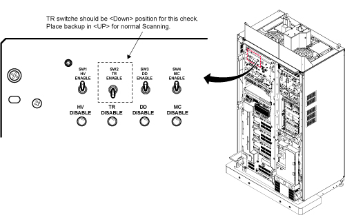
- Place the RF ENABLE switch on front of exciter in the DISABLE (Down) position.
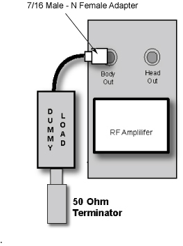
- Remove the Body RF cable from J4. Connect the RF dummy load
into J4. Use 7/16 Male - N Female Adapter attached in System Cabinet.note:
If the body section of the 1.5T CSA Max Power RF Output and Calibration procedure was just completed, configuration is the same. You can leave the head RF cable disconnected and body can keep the wattmeter in line. It will not change the outcome of the calibration.
note:7/16Male -N Female Adapter is located at System Cabinet Left Shelf. Remove left cover and find it. See Figure 2Figure 2. Built In Service Tool
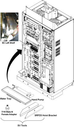
Figure 3. Plug the Dummy Load into J4, Body Out
- Place the RF ENABLE switch in the ENABLE (Up) position.
1.2 Setting up Software Tool to Calibrate UPM – Body Forward Power
This tool must see a Landmark only. Do not connect the head coil. Simply Landmark on the cradle where the Body Phantom would be.
Procedure
- Press Landmark.
- Press Advance to Scan.
- From the Common Service Desktop:
- Select Calibration Tab
- For the Class A/C service tool, select UPM Tool from the calibration menu and select Click here to start this tool
-
Figure 4 shows an example of the UPM tool.
Figure 4. UPM Main Window
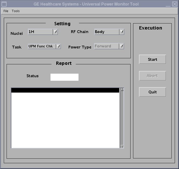
- Select the Nuclei [1H].
- Select the RF Chain you are going to check [Body].note:
Power Type selection will be grayed out. This is normal, and is not used.
- Select: [UPM Func Chk] Button
- Select the [Start] button.
- Select Yes when the prompt asks if the hardware setup is correct.
- To proceed:
- If any one of the tests fail, refer to Troubleshooting UPM.
- If all 3 tests pass, proceed to 1.5T 1.5T HEAD UPM FUNCTIONAL CHECK
2 1.5T HEAD UPM FUNCTIONAL CHECK
2.1 1.5T HEAD UPM FUNCTIONAL CHECK Setup
Procedure
- Inhibit TR faults. The Driver Module in the System Cabinet,
(see Figure 1) . Move switch 2 to the TR Disable position.
- Place the RF ENABLE switch on front of exciter in the DISABLE (Down) position.
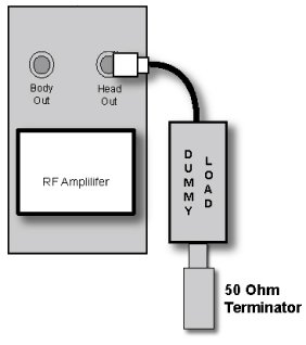
- Remove the head heliax able from J3 at the back of the RF Amplifier
and connect it directly to the RF dummy load.note:
If the Head RF power out procedure was just completed, configuration is the same. You can leave the Body RF heliax cable disconnected and the head output can keep the wattmeter in line. It will not change the outcome of the calibration.
Figure 5. Setup for Head Output Measurement
- Place the RF ENABLE switch in the ENABLE (Up) position.
2.2 Setting up Software Tool to Calibrate UPM – Head Forward Power
-
It is necessary to have a Head coil in place. Don’t connect the head coil. Simply Landmark on the Head Coil.
Procedure
- Withdraw the Cradle from its previous position.
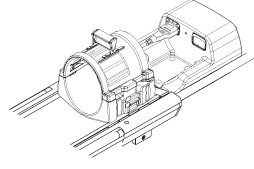
- Place the head coil on the cradle.
Figure 6. Head Coil Setup
- Press Landmark
- Press Advance to Scan
- Select the Nuclei 1H
- Select the RF Chain you are going to check Head.
- Select: UPM Func Chk Button
- Select the Start button.
- Select Yes when the prompt asks if the hardware setup is correct.
- To proceed:
- If all three tests pass, select Quit from the UPM Main Window
- If any one of the tests fail, refer to Troubleshooting UPM.
3 Troubleshooting UPM
Procedure
- Solution 1: Repeat the UPM Functional Test for the receive chain that failed. (Head or Body).
- Solution 2:
- Reset TPS
- Repeat the UPM Functional Test for the receive chain that failed. (Head or Body).
- Solution 3: Reboot the system.
- Solution 4
- Check if RF output power for the failed chain is within specification at TG=200. (Head or Body). If not, re-calibrate RF output power for the chain that failed. Perform Body and Head Maximum Power Setup and Calibration to check the RF output power.
- Repeat the UPM Functional Test for the receive chain that failed. (Head or Body).
4 Finalization
Procedure
- Upon successful completion of the functional check(s):
- Place the RF ENABLE switch on front of exciter in the DISABLE (Down) position.
- Return the system to patient scanning configuration.
- Perform test scan.