Table Up Limit Cable
Prerequisites
Procedure
- Undock patient transport, and move from exam room.
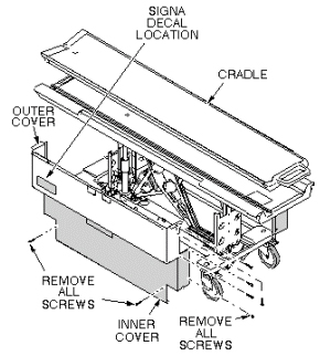
- Remove upper and lower side covers (see Figure 1).
Figure 1. REMOVAL OF PATIENT TABLE COVERS
- Raise table to maximum height.
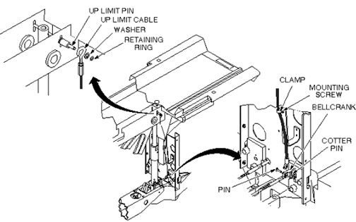
- Remove cotter pin and retaining pin securing bottom end of cable to bell crank (see Figure 2).
- Remove clamp securing cable to bracket (see Figure 2).
- Remove retaining ring and washer securing end of cable to Up Limit pin (see Figure 2).
- Install new cable and attach to Up Limit pin per Step 6 above.
- Fasten other end of cable to bell crank, and secure retaining pin with cotter pin (see Figure 2).
- Attach clamp securing cable to bracket (see Figure 2).
Figure 2. TABLE UP LIMIT CABLE REPLACEMENT
- Adjust table Up Limit cable to remove any slack when hydraulic cylinder is fully extended.
- Check for proper operation of Up Limit switch when table is docked.
- Replace upper and lower side covers. Note position of Signa
logo on outer covers and position toward front of table (see Figure 3).
Figure 3. REMOVAL OF PATIENT TABLE COVERS
1 Finalization
Procedure
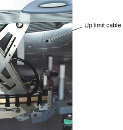
- Verify that tension of up limit cable is appropriate (not too tight and not too loose). Refer to illustration.
Figure 4. tension of up limit cable
- Verify that there is no part caught by wire or any movable module.
- Verify that LPCA is withdrawn to catch the cradle when Table is docked and moved to up Limit position. Verify that LPCA is released to the bore when Table is Down or Undocked.
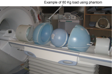
- Place the 80Kg Load evenly on the Cradle. If using the phantom, refer to the following illustration.
Figure 5. 80Kg Load
- Verify that Table moves up and down fully and smoothly using the pedal of Table.
- Verify that Table moves up and down fully and smoothly using the pedal of Dock.
- Verify that all of the parts and the screws are installed.
- Verify that there is no wound or dirt on the Table, Cradle, Pad, and Patient Strap.