System Gain Head Calibration
Prerequisites
1 Head System Gain Calibration
Procedure
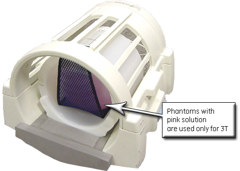
- For systems with the new Split-Top Head Coil, position the SNR
Sphere in the head loader as shown.
Figure 1. Positioning SNR Sphere in Head Loader
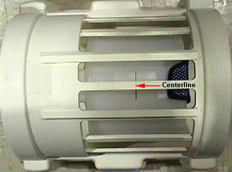
- Fasten the strap to the top of the Head Loader to secure the
SNR Sphere in the loader. Position the head loader on top of the Head
TLT Loader Holder in the head coil (as shown), so the loader is centered
and the loader axial mark is at the center of the head coil window.
Figure 2. Landmarking Head SNR Sphere
- For systems with the Quad Head Coil, position the DQA Phantom
in the head coil.
- Turn on the alignment lights, and align so the center of the DQA Phantom matches the axial beam.
- Place the Head TLT Sphere in the Head Loader, and fasten the strap to the top of the loader to secure the sphere.
- Remove the DQA Phantom and replace with the Head Loader/Sphere, centering it using the axial alignment lights.
- At the keypad on the front of the magnet enclosure, press Landmark and Move to Scan.
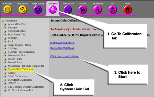
- Go to the Service Desktop and start the Service Browser if not
already running. Start the System Gain Calibration as shown below.
Figure 3. Starting System Gain Tool
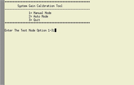
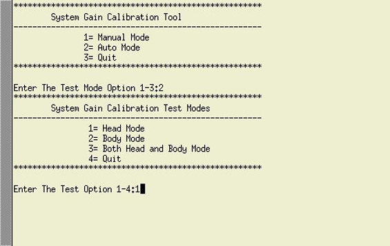
- After the tool starts, type 2 and press Enter for Auto Mode shown below.
Figure 4. Selecting Auto Mode
- Type 1 and press Enter for Manual Mode to begin the test.
Figure 5. Selecting Head Mode
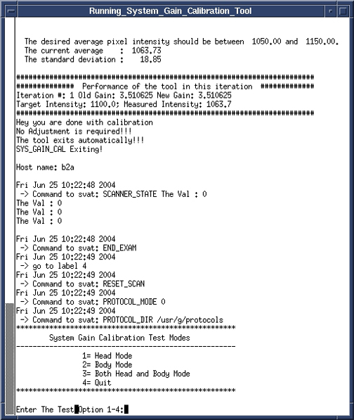
When testing is completed, one of two responses will display:
-
One will indicate the calibration is done and no adjustments are required.
-
The other message will ask if the new Recon Scale Factor should be saved. Type Y and press Enter to save the new calibration file.
Figure 6. Calibration Output
-
- When finished, type 4 and press Enter to exit the tool.
2 Finalization
Procedure
- Remove all phantoms from the system.
- Perform a check scan to ensure system operation.