Patient Table Hydraulic Pump Assembly
Prerequisites
1 Remove Hydraulic Pump Assembly
Procedure
- Undock patient transport, and move it out of exam room.
- Remove both outer covers by removing mounting screws (see Figure 1).
Figure 1. REMOVAL OF PATIENT TABLE COVERS
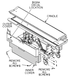
- Remove inner covers by removing mounting screws.
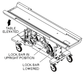
- Raise table to up position.
 warning
- Unhook lock bar spring and move lock bar to horizontal position,
as shown in Figure 2, then lower table until lock bar is supporting
table in its full up position.
Figure 2. PATIENT TABLE LOCK BAR
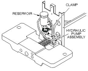
- Disconnect the two hydraulic lines to hydraulic pump assembly,
and fasten upward and aside to avoid excess spillage. Immediately
fold and clamp the translucent (yellow) hose from reservoir to prevent
oil from draining from the reservoir (see Figure 3).
Figure 3. HYDRAULIC PUMP ASSEMBLY
- Loosen two mounting screws attaching upper drip pan to lower drip pan (see Figure 4).
- Remove upper drip pan (see Figure 4).
Figure 4. UPPER AND LOWER DRIP PANS
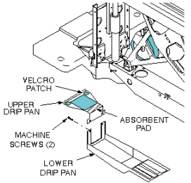
Figure 5. HYDRAULIC PUMP PULL RODS
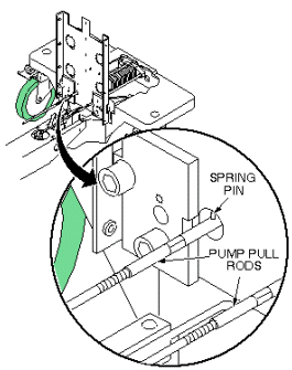
- notice
- Compress main pump spring, as shown in Figure 7, to remove tension from pull rods. Block the pump Up pedal fully up to take its weight off of the pull rods.
- Push the yoke back and unscrew the pull rods form the pump linkage
(see Figure 6).
Figure 6. HYDRAULIC PUMP PULL RODS
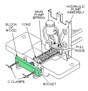
- Remove c-clamps used to compress main spring, as shown in Figure 7.
Figure 7. COMPRESS HYDRAULIC PUMP MAIN SPRING
- Remove machine screw securing bumper to the pump piston (see Figure 8).
Figure 8. HYDRAULIC PUMP REPLACEMENT
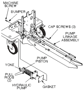
- Remove three mounting cap screws that secure pump assembly to front table support.
- Remove hydraulic pump assembly and gasket.
- If absorbent pad attached to upper drip pan appears to be saturated with fluid, remove it and squeeze out fluid.
 |
2 Install Replacement Hydraulic Pump Assembly
Procedure
- Prepare replacement pump for installation by applying Locktite 242 to three mounting screws and to machine screw that secures bumper to pump piston.
- Set replacement pump assembly on front support of table, making sure that gasket is installed properly, and secure with three mounting screws (see Figure 8).
- Secure the bumper to the pump piston with machine screw.
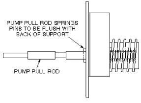
- Reinstall c-clamps on front support, as shown in Figure 9,
to compress main pump spring. Screw pump pull rods into pump linkage,
alternately tightening each side to avoid side loading the pump. Stop
when the rear spring pin on each pull rod is 1/8-inch (3.2 mm) from
pump body (flush with back surface of front support) (see Figure 10).
Figure 9. COMPRESS HYDRAULIC PUMP MAIN SPRING
Figure 10. PUMP PULL ROD ADJUSTMENT
- Connect two hydraulic lines to hydraulic pump assembly (see Figure 11).
Figure 11. HYDRAULIC PUMP ASSEMBLY
- Attach upper and lower drip pans (see Figure 12).
Figure 12. UPPER AND LOWER DRIP PANS
- Block open the Down valve, and pump the Up pedal at least 20 full strokes to purge air from the lines.
- Close Down valve and raise table.
- Retract lock bar and secure with spring, then lower table.
- Fill table reservoir so that fluid is 1/4 to 1/2 inch above
full line when table is at its lowest position.note:
If any air gets into the cylinder, open the hydraulic cylinder bleed screw, when the table is raised, until air is removed from the cylinder. Very little fluid loss should occur during a normal bleed procedure.
- Verify that pump pull rods are adjusted equally by comparing
position of rear spring pins on pump pull rods (see Figure 13).
Figure 13. PUMP PULL ROD ADJUSTMENT
- Replace inner and outer covers. Note position of Signa logo
on outer covers and position toward front of table (see Figure 14).
Figure 14. REMOVAL OF PATIENT TABLE COVERS
3 Finalization
Procedure
- Dock the Table and move the Table to the up limit position. Verify that the Table and Bridge are horizontally aligned and there is no height difference of Table and Bridge at right and left position.
- Verify that there is no part caught by wire or any movable module.
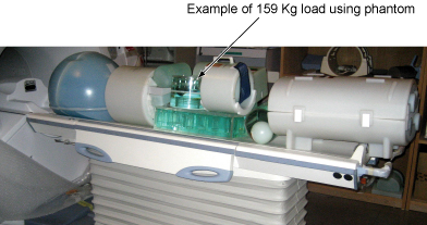
- Place the 159Kg Load evenly on the Cradle. If using the phantom,
refer to the following illustration.
Figure 15. 159Kg Load
- Verify that Table moves up and down fully and smoothly using the pedal of Table.
- Verify that Table moves up and down fully and smoothly using the pedal of Dock.
- Verify that Cradle moves in and out fully and smoothly.
- Verify that the amount of oil is properly filled.
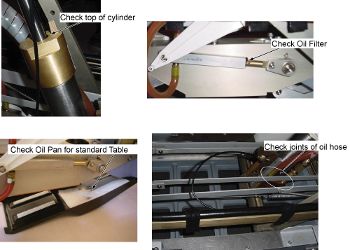
- Verify that oil is not leaked from the cylinder. Refer to following
illustration for check points.
Figure 16. Oil Leak Check
- Verify that all of the parts and the screws are installed.
- Verify that there is no wound or dirt on the Table, Cradle, Pad, and Patient Strap.