PAC Manual Test
Prerequisites
This procedure tests the data paths in both directions from the PAC to the STIF
Procedure
- Go to the Service Desktop and start the Common Service Browser then go to the Diagnostic Tab
and select under Hardware Location, Magnet Room, PAC Manual Tests.
See Figure 1.
Figure 1. PAC Manual Tests
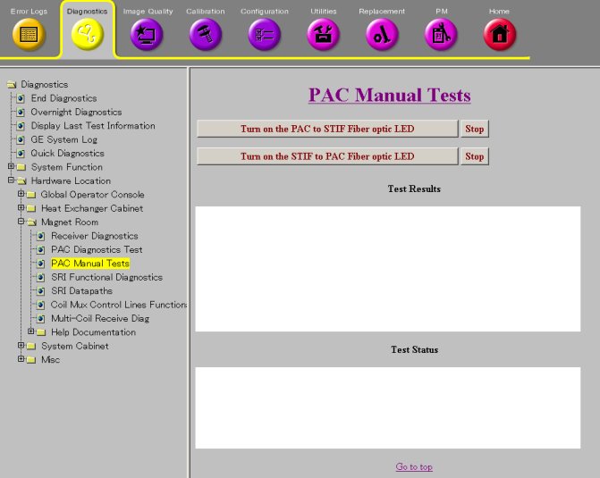
- The PAC to STIF LED test causes the PAC module to turn on the
fiber optic driver LED that is normally used to send serial messages
from the PAC module to the STIF board in the CAM Lite chassis. The
test allows you to visually inspect the PAC serial transmitter and
the fiber optic cables that connect to it.
- Start the test by clicking on the Turn on the PAC to STIF Fiber optic LED button.
- Disconnect the output fiber cable on the PAC to inspect the
LED. If it is ON, then the transmitter is working.
Figure 2. PAC
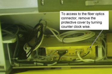
- Reconnect the PAC fiber cable.
- Click on the Stop button to stop the test.
- The STIF to PAC LED test causes the CAM Lite chassis to turn
on the PAC serial port transmitter on the STIF board. This test allows
you to visually inspect the STIF serial transmitter and fiber optic
cables that connect to it.
- Disconnect the PAC output fiber cable on the STIF. STIF is located
in the Rear of System Cabinet.
Figure 3. STIF Board
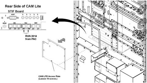
- Click on the Turn on the STIF to PAC Fiber Optic LED button to start the test.
- Inspect the LED. If you can see it then the system is working correctly.
- Stop the test by clicking on the Stop button.
- Reconnect the PAC Fiber cable.
- Disconnect the PAC output fiber cable on the STIF. STIF is located
in the Rear of System Cabinet.
Finalization
No finalization steps.