Longitudinal Drive Motor and Gear Box Replacement
Prerequisites
1 Longitudinal Drive Motor Replacement
The Longitudinal Drive is located in the rear pedestal. Two people are required to replace the Longitudinal Drive Motor due to its strong attraction to the magnet. The motor must be removed from the Magnet Room prior to replacement.
Procedure
- Perform LOTO on the PDU. See the MR Service Safety Manual, PN 5452735.
- Remove the rear pedestal left side cover (as viewed from the rear of the magnet).
- Disconnect the cables from the motor.
- Loosen the two upper set screws on the coupling between motor
and gear box. Rotate the motor axis and coupling by hand in order
to get an access to both hex screws on the coupling.
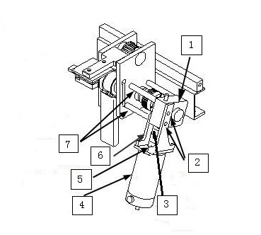
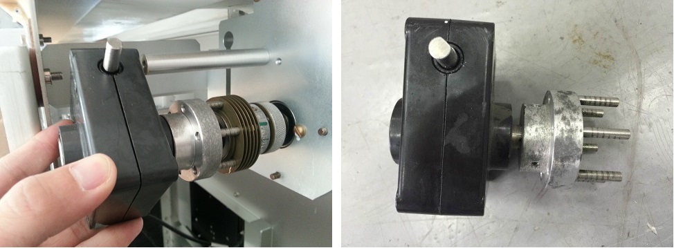
Figure 1. Interim Drive Assy
 caution
- While one person holds onto the motor firmly with both hands,
the other person should remove flat-head screws and nuts that secure
the gear box to the bridge.
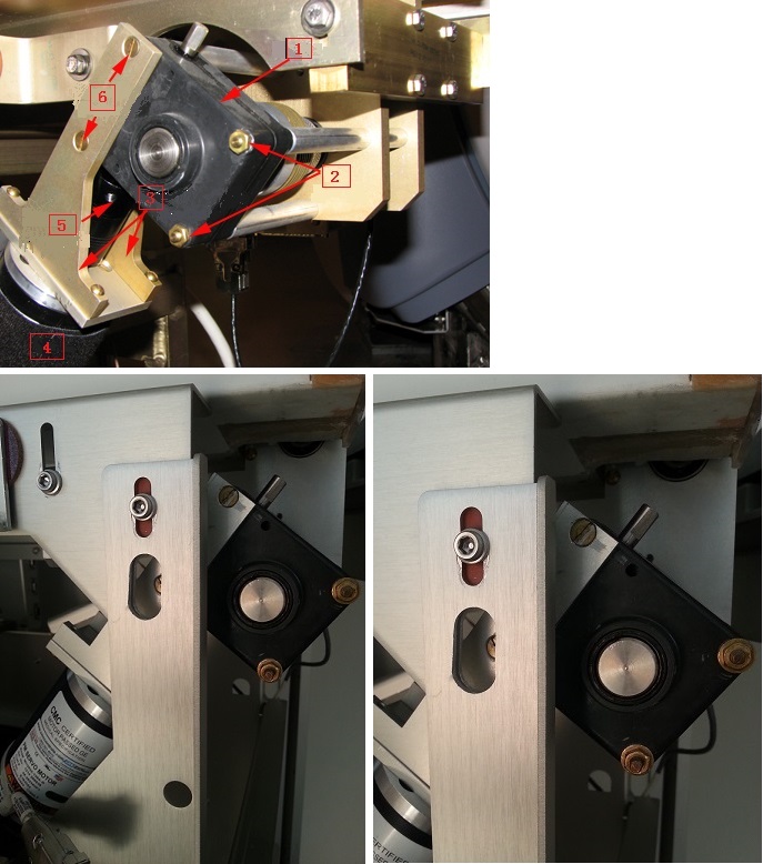
Figure 2. Mounted Drive Motor Assembly
- With the last screw removed, take off the motor and its frame
from the bridge. Then carefully remove the motor from Magnet Room
by placing the motor on the floor and against the wall farthest from
the magnet. The service path to take the motor out of the scan room
is shown in Figure 3.
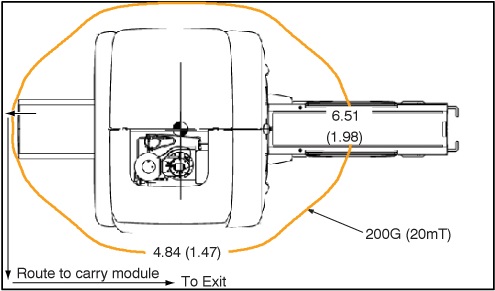
Figure 3. 200G Line and Route to Carry Module
- With the motor outside of
the Magnet Room, remove the frame and coupling. Replace the failed
motor with the new one.
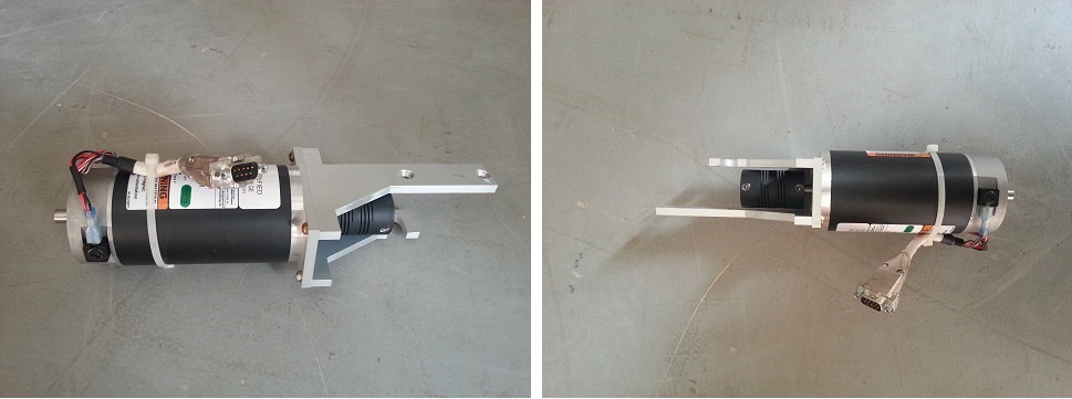
Figure 4. Motor
- Carefully bring the motor and bracket assembly into the Magnet Room along the same path used to remove the assembly.
- To reinstall the motor and bracket assembly in the Rear Pedestal, ensure that a second person holds onto the motor firmly with both hands, while the first person reconnects the motor and bracket assembly to the gear assembly. Tighten the screws and nuts to secure the motor frame.
- Tighten the two set screws on the coupling to finish the motor installation. Make sure one of the hex set screws must be in front of axis flat to prevent free rotation under the load.
- Reattach the cables to the motor and the cover to the pedestal.
- Remove LOTO and restore system power.
 |
2 Gear Box Assembly Replacement
Procedure
- Perform LOTO on the PDU. See the MR Service Safety Manual, PN 5452735.
- Remove the rear pedestal left side cover (as viewed from the rear of the magnet).
- Disconnect the cables from the motor.
- Loosen the two upper set screws on the coupling between motor and gear box. Rotate the motor axis and coupling by hand in order to get an access to both hex screws on the coupling. See Figure 1.
- caution
- While one person holds onto the motor firmly with both hands, the other person should remove flat-head screws and nuts that secure the gear box to the bridge. See Figure 2.
- With the last screw removed, take off the motor and its frame from the bridge. Then carefully remove the motor from Magnet Room by placing the motor on the floor and against the wall farthest from the magnet. The service path to take the motor out of the scan room is shown in Figure 3.
- Take off the gear box together with half of its clutch. The
clutch connecting the gear box and the shaft can be pulled in half
in axial direction.
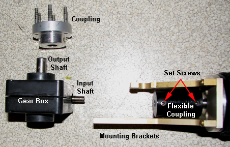
Figure 5. Take off Gear Box
- Loosen the two set screws and remove the half clutch.
Figure 6. Disassembled Drive Motor Assembly
- Install the new gear box in a reverse sequence. Make sure one of the hex set screws must be in front of axis flat to prevent free rotation under the load.
- Carefully bring the motor and bracket assembly into the Magnet Room along the same path used to remove the assembly.
- To reinstall the motor and bracket assembly in the Rear Pedestal, ensure that a second person holds onto the motor firmly with both hands, while the first person reconnects the motor and bracket assembly to the gear assembly. Tighten the screws and nuts to secure the motor frame.
- Tighten the two set screws on the coupling to finish the motor installation. Make sure one of the hex set screws must be in front of axis flat to prevent free rotation under the load.
- Reattach the cables to the motor and the cover to the pedestal.
- Remove LOTO and restore system power.
|
3 Finalization
Procedure
- Run SRI Motion Test.
- Perform Longitudinal Drive Calibration.
- Perform DQA Tool to adjust Isocenter Z.