Longitudinal Drive Motor Alignment to Field
Prerequisites
This procedure must be performed on either a replacement motor, or upon initial system installation to insure that the motor is properly aligned to the magnet field.
Procedure
- Remove power to Long Drive Motor by switching off circuit breakers. Follow all Lock Out and Tag Out procedures by turning off the applicable breaker in the PDU (see Lockout / Tagout for System Cabinet PDU Main Breaker).
- Remove left side cover of rear pedestal.
 caution
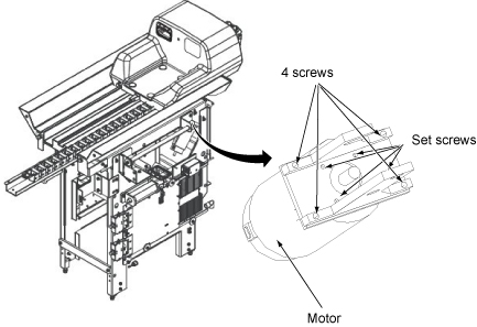
- Remove four mounting bracket screws and loosen lower set screws.
See Figure 1 .
Figure 1. Long Drive Motor Screws
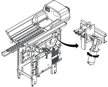
- When the Set Screws are loose, allow the motor to rotate to the magnetic field. See Figure 2
- When the motor is aligned with minimal rotational force, re-tighten
the set screws.
Figure 2. LONG DRIVE MOTOR ALIGNMENT
- Then re-install the four mounting screws.
Finalization
- Remove lock out an tag out devices and return power to the system.
- Verify that pressing IN FAST button on Control Switch Board moves cradle into magnet bore, and that pressing OUT FAST button moves cradle out of magnet bore. If cradle movement is opposite of what it should be, reverse wires on terminals of longitudinal motor.