Interim Drive Assy
Prerequisites
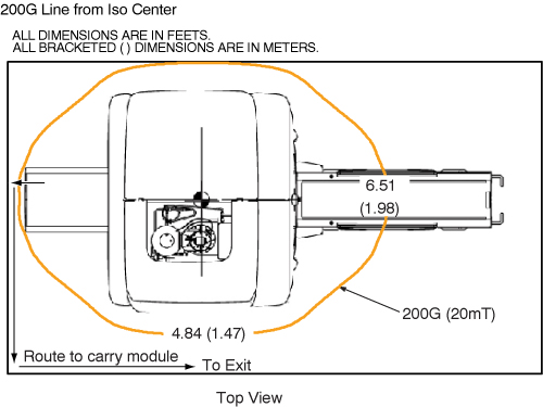
The Longitudinal Drive is located in the rear pedestal. Two people are required to replace the Longitudinal Drive Motor due to the its strong attraction to the magnet.
Procedure
- Remove all covers from Rear Pedestal. Refer to Cover Removal
- Remove cover of Bridge end.
- Remove the LPCA cover.
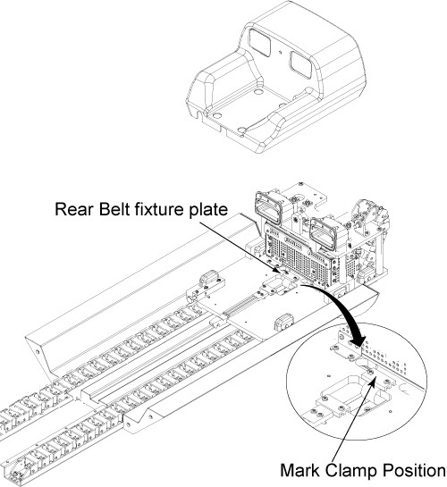
- Mark on the belt at the edge of fixture plate with white pen so that the belt tension can be restored it is after the replacement.
- Release Drive Belt tension by flipping lever under Rear Pedestal.
- Remove rear belt fixture plates through removing 2 screws.
Figure 1. Remove Rear Belt Fixture Plate
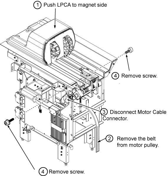
- Remove the LPCA from the Rear pedestal, push the LPCA to magnet side.
- Remove the Belt from Motor Assy.
- Disconnect motor cable connectors.
- Remove 2 cap screws from both side of rear pedestal.
Figure 2. Fixing Screw of Drive Motor Assy
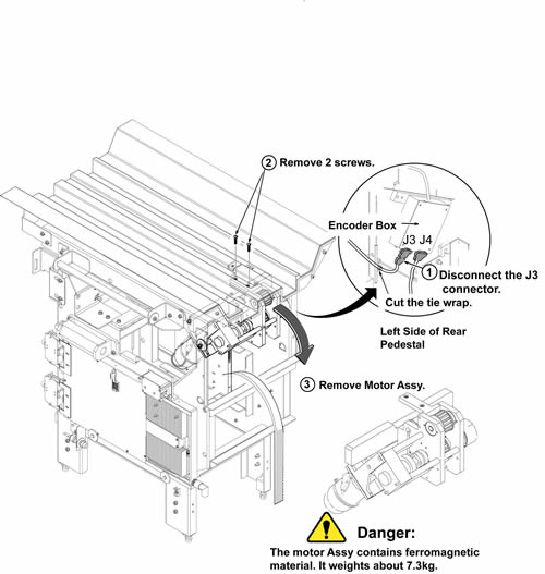
- Cut the tie wrap and disconnect J3 of encoder connector from Encoder Box.
 caution
- caution
- Hold the Motor Assy below the bridge and remove the 2 screws on the bridge.
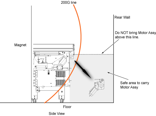
- Carefully slide motor assy to the rear direction and remove
it toward the rear wall below the original motor assy level.
Figure 3. Remove Motor Assy
- With two people holding the motor assembly, exit the magnet room by walking as close to the wall on the coldhead side of the magnet as possible.
- Restore it by the reverse order of the removal.
 |
|
Finalization
- Restore the Power. Refer to Lockout / Tagout for System Cabinet PDU Main Breaker.
- Perform Longitudinal Drive Calibration.
- Perform DQA Tool to adjust Isocenter Z.