Head Coil SNR Test
Prerequisites
Follow this process to prepare for the SNR test using the GE 1.5T HDe Split Head Coil
-
GE Part number 5145658
1 Scanner Verification
Perform system level Signal to Noise Check. Refer to Service Methods CD; Functional Checks; System Level Functional Checks; Signal to Noise Check.
2 Coil Imaging Performance Verification
2.1 Explanation of Procedure
The split head coil can be used in one (1) mode of operation and has one (1) coil name: HEAD. Refer to the Data Sheet 3-5 to understand the data required to calculate the individual element SNR. All ROI measurements are made on the individual element images, not on the composite image. The image quality check uses two different protocols for signal and noise image acquisition. The signal scan is an FSE sequence used to minimize susceptibility and B0 inhomogeneity effects. The noise scan is a GRE sequence that has a Control Variable (do_noise) to eliminate the transmit RF completely during the scan. The signal scan must be run prior tothe noise scan as the R1, R2, and TG values from the signal scan are used for the noise scan.
Procedure
2.2 Signal Scan
Procedure
- From the Scan Desktop, start new scan by selecting [New Pt]; set Patient ID to “geservice” and Patient Weight to “111” pounds. Click [Patient Position] to open protocols window.
- Remove all other surface coils from the cradle. Place the Split Head
Coil on the patient table with the BNC connectors extending into the magnet.
Lock the baseplate into the table slots. Connect the QD box/QHTR to the
BNC connectors on the coil and the connector on the MR unit. The cables from
the QD box/QHTR to the head coil should always be straight, with no crossovers
or loops evident from the outside.
Remove any pads from the coil. Unlock and remove the top half of the coil by depressing the latches on either side of the coil. Set the phantom into the coil and re-attach the top half of the coil.
- At the magnet, press “Alignment Light” button to turn on the light. Move the cradle to align the coil to the alignment lights. Press “Landmark” button to landmark the alignment.
- . Move the coil to scan position by pushing the “Move to Scan” button, ensuring cable does not get snagged.
- At the console, set the protocols per the Signal section from Table 4: Signal and Noise Protocols.
GE Service Personnel can use the Head SNR Signal protocol in the GE / Other
protocol folder.
- Click [Save Series] to download the protocols, then click [Prepare to Scan].
- Run [Auto Prescan]. Take note of the R1, R2 and TG values.
- Run [Scan].
2.3 Noise Scan
A signal scan must be run prior to the noise scan as the same R1, R2 and TG values must be used for both the signal and noise scans. Do not run an Auto Prescan prior to the noise scan as the values will be changed.
Procedure
- Copy the signal scan series. Use [Copy Series] (highlight signal series and click right mouse button) and [Paste Series] in RX Manager. GE Service Personnel can use the Head SNR Noise protocol in the GE / Other protocol folder.
- Click [View Edit] and set the protocols per the Noise section from Table 4 Signal and Noise Protocols.
- Click [Save Series] and click [Prepare to Scan].
- Open [Display CVs] menu under [Research Operations]. Set the “rhformat” and “do_noise” CVs to “1”.
- Run [Manual Prescan], do not make any changes, and click [Done].
- Run [Scan].
2.4
Procedure
3 SNR Image Analysis
Procedure
- Perform SNR Measurement.
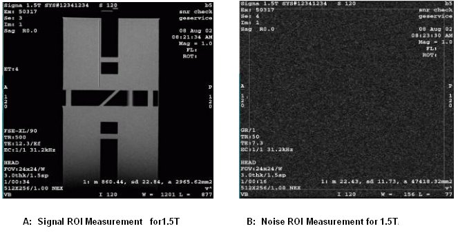
A rectangular ROI should be used for the signal and noise measurements for 1.5T. For Noise scan choose 100% of Rectangular ROI.
ROIs in both signal and noise images can be measured directly in the image browser. Click the user interface button [MEASURE], select the rectangular shape, and adjust its size and orientation so that the ROI is similar to those found in Figure 1.select the circular ROI as 80% of the phantom image. The ROI appear in the lower right corner of the image. Mean, standard deviation, and area of the ROI will appear in the lower right corner of the image.
Record the values for mean signal and mean noise and SNR inTable 6
Individual receiver SNR is defined as the mean of data within the signal ROI divided by the mean of data within the noise ROI (with a correction factor).
note: The SNR calculation uses the MEAN of the signal image and MEAN of the noise image.Figure 1.
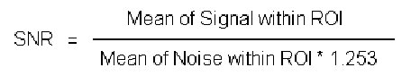
Figure 2. Signal and Noise Image
- Check that the result satisfies the specification.
The SNR measurements must be greater than or equal to the following specifications:
note: Image 1 and image 5 are collected to verify that the phantom is correctly centered. For example, you would want images 1 and 5 to be the same size. If they are not the same size, then the phantom should be repositioned relative to the coil center.
4 External Cable Check
No cable continuity checking is recommended for the connector because of pin damage concerns.
5 Mechanical Hardware Check
Check the BNC cables for mechanical damage and shorted center pins. Inspect the Bendix/Hypertronics connector for damage from improper insertion. Banana plug on the 1.5T/1.0T Bendix Quick Disconnect plug will damage pins if the operator attempts to insert the connector upside down. At this time also inspect the Bendix/Hypertronics connector for foreign material and remove as appropriate. Make sure cradle latches and top latches are operating and still have adequate range of motion.
6 SNR Data Sheet
Procedure
- Enter in Data Sheet.
Use the table provided below to record the calculated signal to noise ratio (SNR) data obtained from the Functional Checks section.
7 Finalization
Finalization
No finalization steps.