Gradient Polarity Checks
Prerequisites
Reversal of the polarity of a single gradient causes the right/left or top/bottom reversal of the images from two axes, and reversal of the offsets for one axis. Incorrect polarity of all of the gradients causes the images from all planes to be upside down and backward, and causes the system to scan offset images in the opposite direction from those commanded for all axes.
The values mentioned in this procedure are related to the physical x, y, and z gradient amplifiers, respectively. The values for setting x-, y-, and z-gradient to obtain 1 gauss/cm, respectfully, are in the system configuration file.
Procedure
- At the operator workspace, select the SCAN icon
- Click on New Pt to enable setting of a new landmark.
- the following:
Id: geserviceEnter
Name: gradient polarityEnter
Weight (Lb.): 111Enter
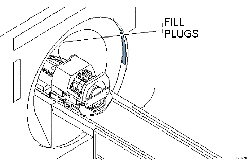
- Place the DQA-III phantom and loader in the head coil. Position it with
the fill plugs up, and toward rear of magnet (see Figure 1).
Figure 1. DQA PHANTOM POSITIONING
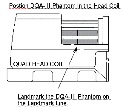
- Landmark in the sagittal and axial planes (DQA-III coronal plane is
not at isocenter). See Figure 2for
positioning the phantom in the quad head coil.
Figure 2. LANDMARKING DQA-III PHANTOM
- At front enclosure on scanner, press LANDMARK, then MOVE TO SCAN.
- At the Operator Workspace, prepare the system for a “Geometry
Verification, Coronal” scan using the scan protocol found in
- Click on Scan (system auto prescans first).
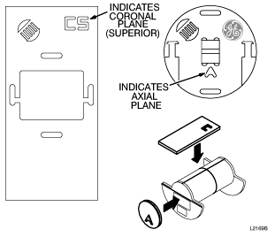
- On the scan desktop, click on Autoview. When
the image displays, verify that the CS appears in the upper right-hand corner
(see Figure 3).
Figure 3. DQA-III PHANTOM GEOMETRY
 note:
note:Top/bottom reversal is caused by improper z-gradient polarity (wires crossed between output of Gradient Amplifier and input of Gradient Coil). Left/right reversal is caused by improper y-gradient polarity.
- At the Operator Workspace, click on New Series.
- At the Operator Workspace, prepare the system for a “Geometry
Verification, Axial” scan using the scan protocol shown in Table 5
- For TwinSpeed, select GradMode=WHOLE.
- Click on Save Series
- In the RX MANAGER window, click on Prepare to Scan.
- Click on Scan (system Auto Prescans first).
- When the axial image displays, verify that the A appears in the lower-middle
of the image. The image should have the GE logo in the upper right-hand corner
(see Figure 3).note:
Left/right reversal is caused by incorrect polarity of the X gradient. Top/bottom reversal is caused by improper Y gradient polarity.
- For TwinSpeed, repeat scans for GradMode=ZOOM.
- In the RX MANAGER window, click on End Exam to exit.
Finalization
- Put away any phantoms and any other tools used for the test.
- Return to Geometry Verification Start Page or Go back to Software Configuration Checks