Front Bridge Assembly
Prerequisites
Procedure for replacing the patient transport split bridge. Plan on about 30 minutes to remove the bridge. Double the time if you are reinstalling the same bridge components. Plan on at least 75 minutes if you are installing a new bridge that has to have the subcomponents assembled (see Replacing Bridge with Part Number 5137313).
1 Removing Front Bridge
Procedure
- Move the LPCA to rear pedestal with IN button of magnet front panel. Then, Separate LPCA from cradle.
- Move the Cradle to the home position and undock the patient table.
- System Power must be turned OFF. Refer to System Cabinet PDU Main Breaker LOTO Procedure.
- Remove following covers.
-
R/L Rear pedestal covers (Refer to Rear Pedestal Cover.)
-
LPCA cover (Refer to LPCA Cover Removal.)
-
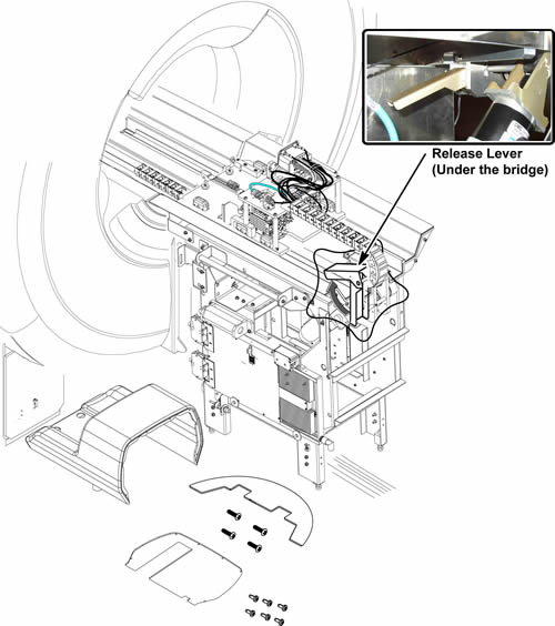
- Release drive belt tension by flipping lever under rear pedestal.
Figure 1. Belt Tension Arm
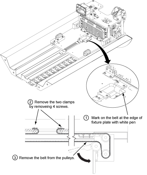
- Remove the two belt clamps of from LPCA. Refer to illustration. (see Figure 2)
- Remove the belt from the pulleys of rear pedestal.
Figure 2. Note the number of Belt Notches beyond the Belt Clamp
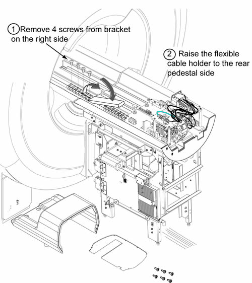
- Remove the flexible cable holder from the front split bridge by removing 4 screws.
- Raise the flexible cable holder to the rear pedestal side. Refer
to illustration.
Figure 3. Raise the flexible cable holder
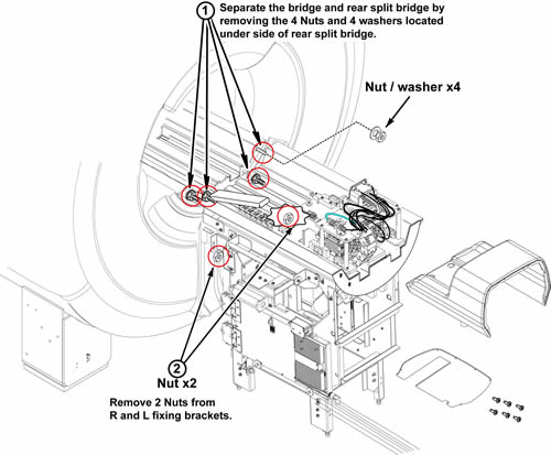
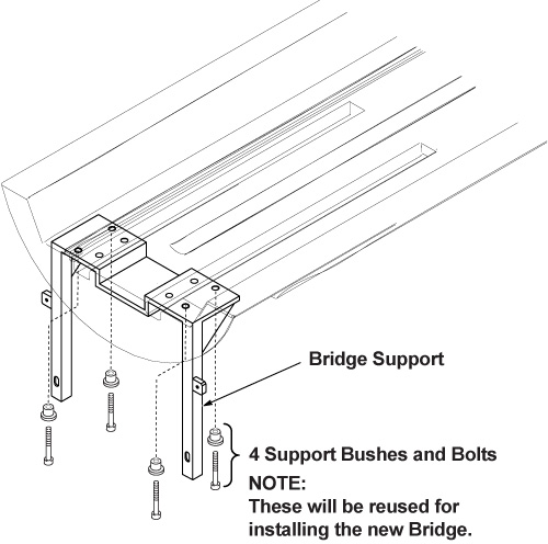
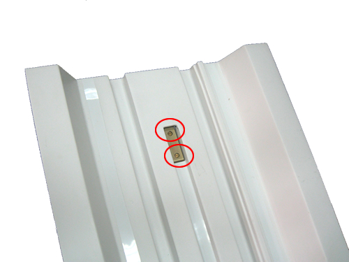
- Separate bridge from rear split bridge by removing 4 nuts and
4 washers and removing 2 nuts from R and L fixing brackets.
Figure 4. Separate bridge from rear split bridge
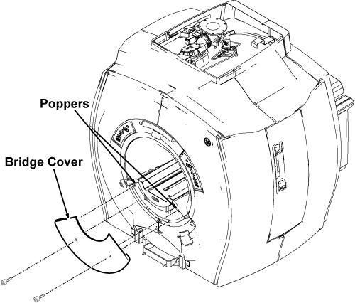
- Remove the bridge cover by removing two M5 bolts.Figure 5 shows the procedure
for Optima MR360 Configure, for Brivo MR355 configure, uninstall the
fixed table first following the procedure in Fixed Table Replacement,
and then follow the same procedures shown in Figure 6
Figure 5. Lower Cosmetic Cover
 caution
- Remove the bridge from the magnet bore.
Figure 6. Bridge Bracket Height Adjustor and Spacer
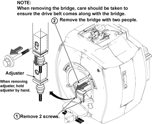 note:
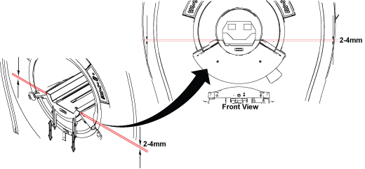
note:If you are going to put this bridge back, do not change the location of the Height Adjustment's threaded nylon nuts. If you are replacing this bridge with a new bridge, adjust the lower nuts so the edge of the bridge adjacent to the end bell is 2-4 mm above the flat surface of the end bell.
Figure 7.
- Slide the bridge out from magnet. Care should be taken to ensure the drive belt comes along with the bridge.
 |
2 Replacing Bridge with Part Number 5137313
Procedure
- Lay bridge on its top and remove the four (4) M5 Allen bolts
that attach the Bridge Mounting Bracket.
Figure 8. Bridge Bracket Bolt Locations
- Remove belt from bridge.
Figure 9. Pulley with Belt Removed
- warning
- Flip the bridge so the top is facing up. Using a regular screwdriver,
unscrew the two bolts.
Figure 10. Screw Location
 note:
note:When these bolts are removed, the plate on the opposite side will fall out.
- Remove pulley.
Figure 11. Removing Pulley
|
3 Bridge Replacement / Installation
Procedure
- If necessary, reinstall (or install new) Pulley ASM and Drive Belt on to new Bridge by reversing the steps in Replacing Bridge with Part Number 5137313.
- To reinstall the bridge, perform the steps in Removing Front Bridge in reverse order.
4 Finalization
Procedure
- Dock the Table and move the Table to the up limit position. Verify that the Table and Bridge are horizontally aligned and there is no height difference of Table and Bridge at right and left position.
- Verify that Cradle moves in and out fully and smoothly.
- Perform Signal to Noise - Head Scan.