Forward Reverse Quadrature Check
Prerequisites
This section determines the quadrature balance of the quad coil and the phase splitter network. In this test, the Body or Head TLT Sphere phantom is scanned with the quadrature coil connected in two ways. First, an image is taken with the quadrature coil as presently connected. Next, the cables to the quadrature switches are reversed, and the phantom is scanned a second time using the same protocol. The resultant images are analyzed to verify proper quadrature drive function and cable configuration. This procedure consist of the following:
-
Body Forward/Reverse Quadrature Scans.
-
Forward/Reverse Quadrature Test Image Analysis.
1 Body Forward/Reverse Quadrature Scans
Procedure
- To prepare the system for scan, set the following parameters:
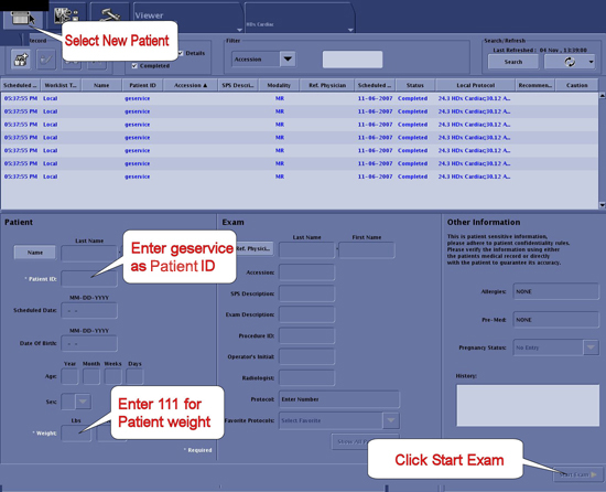
- Click New Pt and then specify these settings:
Figure 1. Scan I/O Page
-
ID: geserviceEnter
-
Name: body f/r quadEnter
-
Weight (lb): 111Enter
-
- Set patient protocols to Service.
Figure 2. Protocol Selector
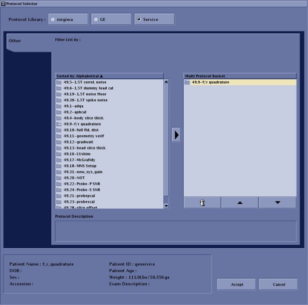
- In the Patient Protocols section, click Service and then click Other.
- Locate Protocol F and R quadrature, click the protocol name, and then click the arrow in between to add it to the Multi Protocol List or remove it.
- Click Accept to download the series.
- Click New Pt and then specify these settings:
- At the scanner, remove any surface or head coil from the bore.
- Place the Body TLT Sphere Phantom in the SPT Body Loader and place the Body Loader/TLT Phantom in the center of the cradle.
- Landmark on the center of the sphere. On the front of the magnet enclosure, press LANDMARK on the keypad, and then press ADV TO SCAN.
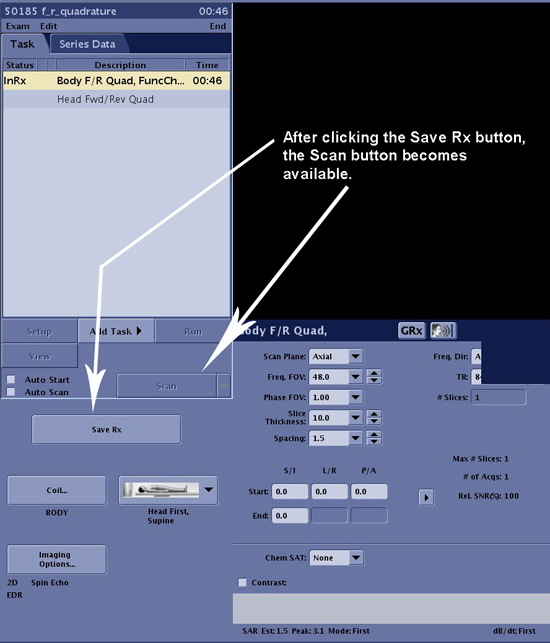
- Start exam then select Save Rx. Then,
perform scan by following steps.
-
Select Manual Prescan from the drop-down list next to the Scan button.
-
Enter the recorded center frequency value for the first installation. Verify that the center frequency peak can be seen at the center of the sceen. Then, select 'Save frequency'.
-
Select Auto Prescan from the drop-down list next to the Scan button.
-
Select the Scan .
Figure 3. Saving Scan Parameters
-
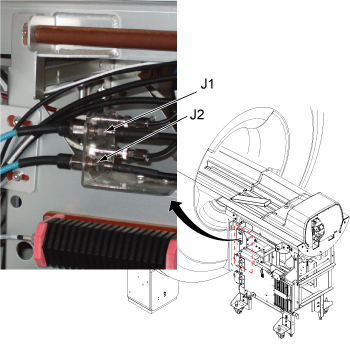
- Reverse the black I and Q cables connecting to J1 and J2 at the bulkhead.
Figure 4. J1 and J2 at bulkhead
- Without changing the prescan settings, rescan the phantom using the same scan protocol.
- Wait until analysis is completed before restoring the system to the original configuration (i.e., return J1 and J2 to their original connection).
2 Forward/Reverse Quadrative Test Image Analysis
This analysis procedure applies only to body scans.
Procedure
- Display each image so you can compare mean values.
- Use a square Region of Interest (ROI) of 4000 mm2 ± 50 mm2, located
at the center of the image. Measure the mean pixel value (MPV1). In
the viewer, this is shown as m=xxx. Jot down this value. See Figure 5.
Figure 5. Image Comparison
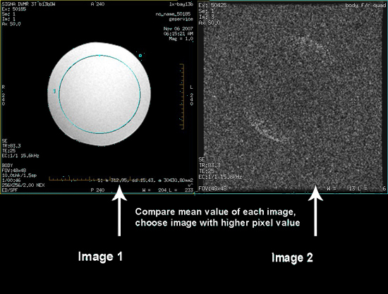
- Display the second image.
- Use a square Region of Interest (ROI) of 4000 mm2 ± 50 mm2, located
at the center of the image. Measure the mean pixel value (MPV2). In
the viewer, this is shown as m=xxx. Jot down this value. See Figure 5.note:
: To use the same ROI box, press CTRL-C on the keyboard for the first image. Move the mouse cursor to the second image and click the left button. Finally, press CTRL-V on the keyboard. This will copy the ROI to the second image.
- Use the cable configuration which produced the highest mean value from the ROI.
3 Finalization
Procedure
- Restore the system to patient scanning condition.
- Do a test scan to ensure the system is running properly.