Express Coil: Head Neck Array Coil ID PCB Replacement
Prerequisites
Follow this process to change the Coil ID PCBs for Express Coil- Head Neck Array.
Procedure
- notice
- Unscrew the bottom cover and remove from coil. Retain the original screws used.
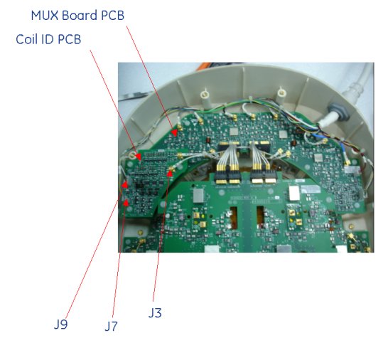
- 2. Identify the Coil ID PCB located on Mux Board. See Figure 1 Identify and
Remove DC Connectors Pins (J7 & J9) and one DC PCX Connector (J3)
on Coil ID PCB.
Figure 1. Mux Board and Coil ID PCB Locations
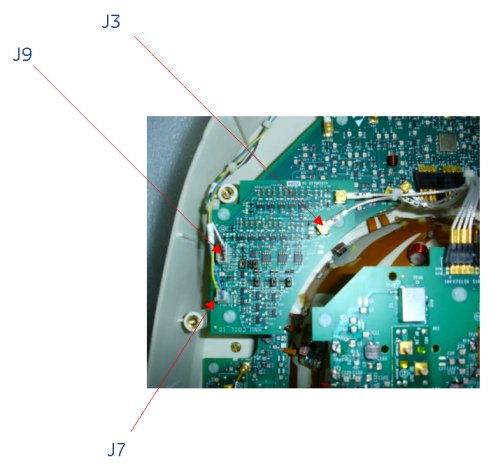
- Unscrew the 3 screws of Coil ID PCB as shown in Figure 2 and carefully
remove the Coil ID assembly. Retain the removed 3 screws carefully.
Figure 2. Mux Board and Coil ID PCB Locations
 note:
note:Ensure that only two DC Connectors (J7, and J9) and one DC PCX Connector (J3) are removed from System Cable.
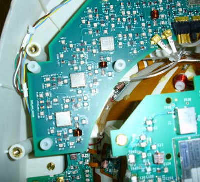
- Mount the new coil ID PCB assembly with 3 screws in the open
slot on the Mux Board. See Figure 3.
Figure 3. Coil ID PCB Locations
- 5. Connect the J7 and J9 DC Connector of System Cable Assy to Coil ID PCB at J7 and J9 as shown in Figure 2. Connect the J3 DC PCX Connector to J3 DC PCX connectors on Coil ID PCB. Verify that all labels on the connectors match those on the Mux Board and Coil ID Board.
- 6. Replace cover. Use original screws to fasten cover.
 |
Finalization
Perform a Perform the MCQA Test.