Express Coil: Head Neck Array Coil Cable Replacement
Prerequisites
Follow this process to change the system cable for coils that have a cable available as a spare part.
Procedure
- notice
- Unscrew the bottom cover and remove from coil. Retain the original screws used.
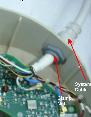
- Unscrew the cable clamp nut from the coil as shown in Figure 1. Retain the original nut used.note:
When re-installing components, the nut must be attached back
Figure 1. Removing the Cable Clamp
- Identify the Mux Board Assembly and the Coil ID PCB located
on the Mux Board (Head Neck Unit (HNU) Only). See Figure 2.
Figure 2. Mux Board and Coil ID PCB Locations
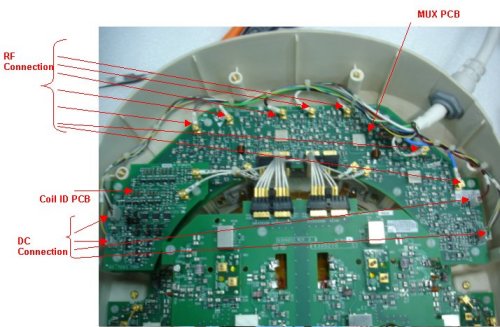
- Identify all the RF (CH1-CH8) Connectors and DC Connectors Pins (J3, J5 and J10on Mux Board and J7, J9 on Coil ID Board). See Figure 2.
- Remove all RF connectors (CH1-CH8) from Mux Board. See Figure 2. Pliers may be necessary for removal of the RF (PCX) connectors, as they may be difficult to unplug. This will help prevent accidental breakage of the cables.
- Remove DC connectors (DC) J3, J5 from MUX Board and J7, J9 from Coil ID PCB. See Figure 2.
- Remove GND connectors –J10 from Mux board assy.
- Remove the system cable (without the coil id).
- Install the new system cable.
- Align the cable into the notch of former slot. Screw down cable clamp nut using the spanner
- Connect RF connectors (CH1-CH8) to Mux Board (CH1-CH8). Verify that all labels on the connectors match those on the Mux Board. See Figure 2.
- Connect DC connectors (J3 & J5) to Mux Boards and J7 and J9 to coil ID PCB. Verify that all labels on the connectors match those on the Mux Board and Coil ID Board. See Illustration 2.
- Connect GND connectors J10 to the Mux Board. Verify that all labels on the connectors match those on the Interface Board. See Figure 2.
- Replace cover. Use original screws to fasten cover.
 |
Finalization
Perform a Perform the MCQA Test.