Express Coil: Anterior Array Cable Replacement
Prerequisites
1 Cable Removal
Procedure
- notice
- Place anterior coil patient side up.
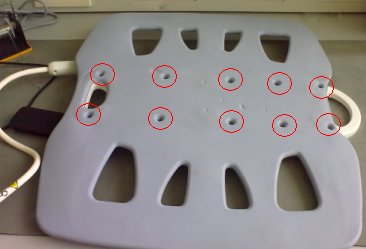
- Remove all 10 screws from the cover as shown in the Figure 1.
Figure 1. 10 screws
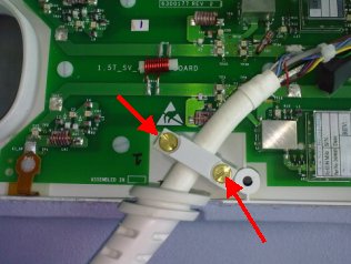
- Unscrew cable clamp. See Figure 2.
Figure 2. Unscrew cable cramp
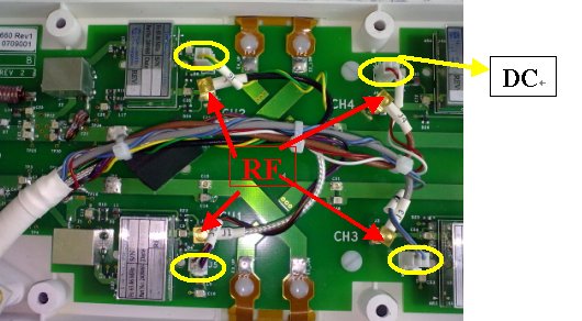
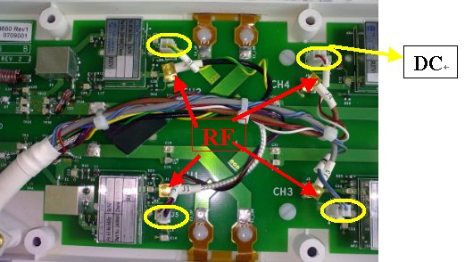
- Locate and disconnect all 4 RF cables and 4 DC cables coming
from the cable assembly. See Figure 3
Figure 3. RF Cable and DC Wire Removal
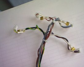
- Remove the cable from the coil. See Figure 4.
Figure 4. Cable Removal
 |
2 Cable Installation
Procedure
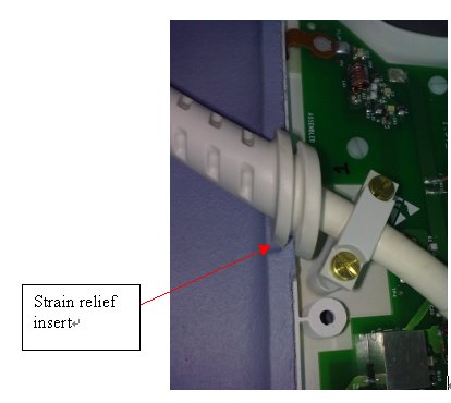
- Place strain relief in cut-out.
Figure 5. strain relief
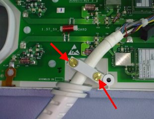
- Align cable with the screw posts.
- Secure cable clamp over cable until tight with the previously
removed brass screws.
Figure 6. brass screws
- Attach the RF wires to J1, J2, J3, J4 and DC wires to J5,J6,J7,J8.
Figure 7. RF wires and DC wires
- Attach the Clear RF cable at J1 (CH1) on the feedboard.
- Attach the Black RF cable to J2 (CH2) on the feedboard.
- Attach the Gray RF cable to J3 (CH3) on the feedboard.
- Attach the Brown RF cable to J4 (CH4) on the feedboad
- Attach the DC wire (Brown+Violet) cable to J5 on the feedboard.
- Attach the DC wire (Green+Yellow) cable to J6 on the feedboard.
- Attach the DC wire (Gray+Blue) cable to J7 on the feedboard.
- Attach the DC wire (White+Red) cable to J8 on the feedboard.
- Replace the cover.
3 Finalization
Procedure
- Perform Express Coil MCQA Test .