ECG Leads Installation and Functional Checks
Prerequisites
1 Test the functionality of the ECG Leads
Procedure
- If not already done, disconnect the ECG cables from the PAC I/O Plate.
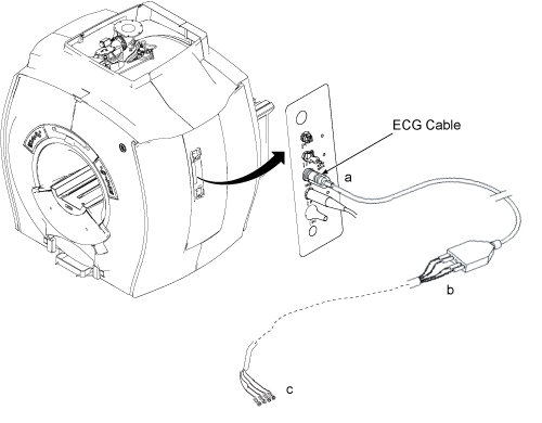
- Check the impedance of the ECG Cables. See Figure 2. From each of the leads at point “a” to the other
end of that lead at point “b” the impedance should be
0 Ohms. From each lead at point “b” to its respective
connection at point “c”, the impedance should be 60k Ohms
±5% tolerance. Figure 1 shows a pin-diagram of the
connection at point “c”
Figure 1. Pin Diagram Of ECG Lead

2 Connect the leads and plug the ECG Leads to the PAC
Procedure
- Connect the white High Impedance MRI ECG Lead wires to the grey ECG Patient cable by matching the colors on the white cable to the colored dots of the grey cable.
- Plug the open end of the grey ECG Patient cable in to the ECG
port of the PAC.
Figure 2. PAC Assembly With ECG Leads Connected
- As an additional functional test of the ECG leads, if there is a cardiac waveform simulator available at the site, connect the leads to the simulator. Open the “Gating Control Screen” from the Scan Desktop. Select “Standard Gating” and cycle through the three different trigger leads, ECG1, ECG2, and ECG3. There should be a cardiac waveform displayed for each of the three trigger lead selections.
3 Finalization
Procedure
- Return the system to the patient scanning condition.
- Do a check scan to insure the system is operating properly.