Cradle Release Tension and Front Guide Roller Height Adjustments
Prerequisites
This procedure provides the instructions for the Cradle Release from the Transport Tension adjustment and the Front Guide Roller Height adjustment on the patient table.
1 Cradle Release from Patient Transport Tension Adjustment
1.1 Cradle Position During Release Mechanism Adjustment
Procedure
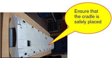
- Make sure the cradle is positioned on the Table.
- Remove the Table from the Scan Room to perform the rest of this service procedure.
- Press the cradle release pin and front Delrin stopper shown
in Figure 1.
Figure 1. Location of Cradle Release Pin and Delrin Stopper
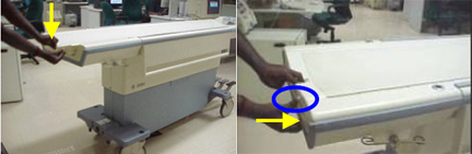
- Pull the cradle out. (The cradle will come approximately 50
mm away from the tabletop front; done to make sure the cradle is clear
of the flipper actuation. See Figure 2.)
Figure 2. Cradle Cleared of Flipper Actuation
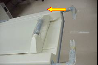
- Press the Up Limit Indicator Bumper to release the central pin
shown in Figure 3.
Figure 3. Up Limit Indicator Bumper
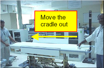
- Pull the cradle out and remove it from the Table. (See Figure 4.)
Figure 4. Removing Cradle from Table
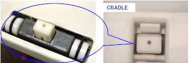
- Once the cradle is removed from the table, place the cradle
on a surface where further adjustments can be performed. (See Figure 5.)
Figure 5. Setting Cradle Aside
1.2 Initial Checks to Adjust Cradle Release Mechanism
Procedure
- notice
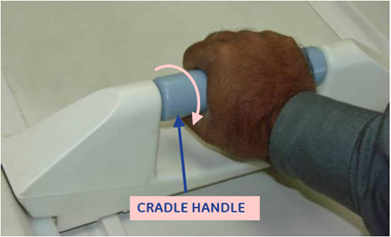
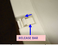
- Twist the handle fully to extend the Release Bar/Ramp as shown
inFigure 6, and hold it in the extended position.
Figure 6. Emergency Cradle Release
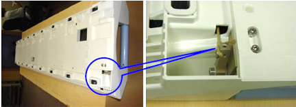
- Refer to Figure 7. Using a socket extension, nut
driver or similar tool, push the Release Bar/Ramp shown in Figure 8 with approximately 10 to 20 lbs. of force (Force
Gauge, 5142800 or 5142800-2).
- Observe the movement of the release ramp. A properly adjusted
release ramp will exhibit some spring, and return to its original
position when released.
Figure 7. Pushing Release Bar/Ramp
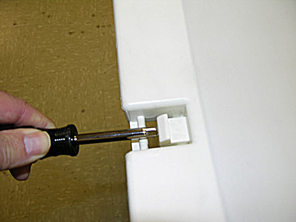
Figure 8. Location of Release Bar/Ramp
- If the Release Bar/Ramp fails to return to its original position
and moves more than approximately 1.5 mm (0.06 in.), refer to Figure 9and adjust the
release mechanism tension according to the instructions in Tension Adjustment of Cradle Release Mechanism.
Figure 9. Failure Example
- Observe the movement of the release ramp. A properly adjusted
release ramp will exhibit some spring, and return to its original
position when released.
 |
1.3 Tension Adjustment of Cradle Release Mechanism
Procedure
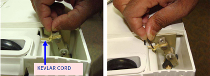
- Turn the cradle over to access the Kevlar cord shown in Figure 10.
Figure 10. Location of Kevlar Cord
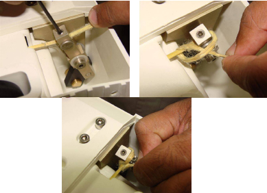
- Remove the knot in the Kevlar cord (shown in Figure 11) with the assistance
of the 3/32 in. Allen Wrench.
Figure 11. Removing Knot in Kevlar Cord
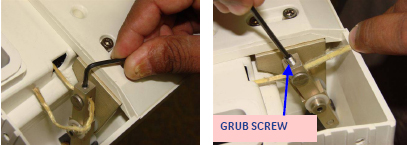
- Using the 3/32 inch Allen Wrench, loosen the grub screw as shown
in Figure 12.
Figure 12. Loosening Grub Screw
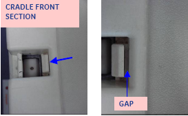
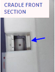
- Pull the Kevlar cord in the direction of the blue arrow shown
in Figure 13to apply the necessary tension required to butt the Release Bar/Ramp
against the cradle front section. See Figure 14.
Figure 13. Applying Tension on Kevlar Cord
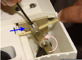
Figure 14. Release Bar/Ramp Against Cradle Front
- notice
- Refer to Figure 15.
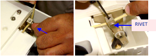
- Once the Release Bar/Ramp has the appropriate tension applied,
tighten the grub screw to secure the tension on the cord.
Figure 15. Securing Kevlar Cord
- Tie a knot with the loose end of the Kevlar cord as shown above.
- Once the Release Bar/Ramp has the appropriate tension applied,
tighten the grub screw to secure the tension on the cord.
-
- If the height of the Front Guide Rollers requires adjustment, proceed to Front Guide Rollers Height Adjustment. If not, proceed to Step 1.
|
2 Front Guide Rollers Height Adjustment
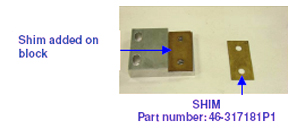
If the Front Guide Rollers require a height adjustment, shims need to be added or removed. The Shim part number is 46-317181P1. Order additional shims if the height is to be raised. The Shims are 0.35 of an inch wide.
Procedure
- If the cradle is not already removed from the table top, follow Step 2, then proceed to Step 1.
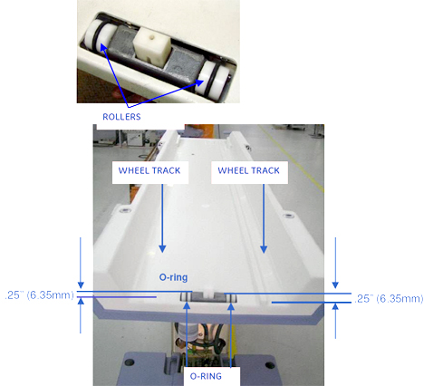
- The Front Guide Rollers should be 0.25 inches above the cradle
wheel tracks as shown in Figure 16. In there is any variation, follow the next
steps in the adjustment process.
Figure 16. Front Roller Guide Height
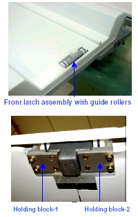
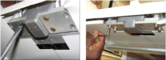
- To readjust the height of the rollers, the latch assembly Holding
Blocks must be removed. (See Figure 17.)
Figure 17. Location of Holding Blocks
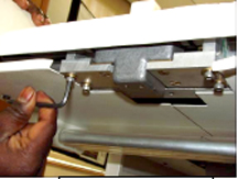
- Using the 5/32 Allen Wrench, loosen the Allen screws while holding
the block. (See Figure 18.)
Figure 18. Removing Allen Screws
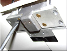
- Using the standard screwdriver, remove the screws from the holding
block as shown in Figure 19.
Figure 19. Removing Holding Block Screws
- Remove the Holding Blocks from the latch assembly.
- Add or remove shims so the O-rings are at the correct height
of 0.25 inches (6.35 mm) above the horizontal wheel track on either
side. (See Figure 20.)
Figure 20. Adding/Removing Shims
- Refer to Figure 21. Once the appropriate height is achieved, install
the Holding Bocks:
- Using the standard screwdriver, loosely secure the screws on both holding blocks.
- Use the 5/32 Allen Wrench to loosely secure the Allen screws on both holding blocks.
Figure 21. Installing Holding Blocks
- Before securing the holding blocks in place, make sure the latch
is centered in the slot of the cradle as shown in Figure 22.
Figure 22. Front Latch Position
- Check the front latch height before securing the holding blocks:
- Return the cradle to the table top.
- With the casting in the docked position, make sure the Delrin stopper is flush and the latch is projected 2 mm from the casting.
- Once the latch is at the proper height, secure the screws holding the holding blocks.
3 Finalization
Procedure
- Re-assemble the cradle by placing the cradle in its position on the table top.
- Connect the table to the scanner.
- Move the cradle into the bore of the scanner and then return to its normal position to make sure the cradle is properly placed on the table top.
- Perform an emergency cradle release by twisting the handle to
release it.
- If it does not release, adjust the tension again.
- If the cradle release functions properly, proceed to Step 5.
- Re-engage the cradle to its functioning position.