Bridge Removal and Replacement
Prerequisites
This procedure explains how to replace the patient transport split bridge. Plan on about 30 minutes to remove the bridge. Double the time if reinstalling the same bridge components. Plan on at least 75 minutes if installing a new bridge that requires subcomponent assembly. (See Replacing Bridge Part within Bridge Assembly.)
1 Removing Front Bridge
Procedure
- Position the LPCA to the far rear of the enclosure, and undock the patient table.
- Detach the cradle from the LPCA.
- Perform LOTO on the PDU for the PEN panel, patient blower, and magnet room. See the MR Service Safety Manual, PN 5452735.
- Release the drive belt tension by flipping the lever under the
rear pedestal.
Figure 1. Belt Tension Arm
- Remove the LPCA cover.
- Count and make a note of the number of notches above the belt
clamp.
Figure 2. Location of Belt Notches Above Belt Clamp
- Unscrew the two Phillips screws that hold the belt clamp plate in place on each of the two belt clamps.
- Pull the drive belt free from the rear pedestal. Carefully unthread
the drive belt from the rear pulley.
Figure 3. Drive Belt Threaded through Rear Pulley
 note:
note:At the rear pedestal, route the drive belt over rear pulleys only. Do not route the drive belt over crossbars or other objects in the rear pedestal. Doing so can overstress the drive system.
- At the rear of the split bridge, use a 17 mm wrench to remove the four M10 nuts and washers that attach the rear pedestal to the split bridge.
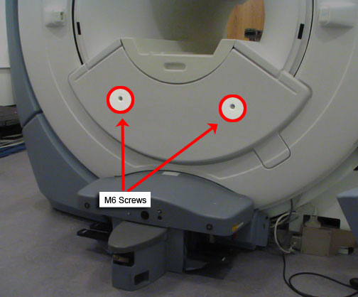
- Using a 5 mm Allen wrench, remove the two M6 screws holding
the front bridge cover in place and remove the cover.
Figure 4. Lower Cosmetic Cover
- Using a 17 mm wrench, remove the two M10 Bridge Bracket bolts.
(When these bolts are removed the height adjuster and spacer will
no longer be secured.)
Figure 5. Bridge Bracket Height Adjuster and Spacer
 note:
note:If reusing this bridge, do not change the location of the height adjustment for the threaded nylon nuts. If replacing this bridge with a new bridge, adjust the lower nuts so the edges of the bridge adjacent to the end bell are flush to 1 mm below the flat surfaces of the end bell.
- Slide the bridge out from magnet, making sure the drive belt comes along with the bridge.
2 Replacing Bridge Part within Bridge Assembly
Procedure
- Lay the bridge on its top and use a 5 mm Allen wrench to remove
the four M6 Allen bolts that secure the bridge mounting bracket.
Figure 6. Location of Bridge Bracket Bolts
- Remove the belt from the bridge.
Figure 7. Pulley with Belt Removed
 warning
- Flip the bridge so the top is facing up. Using a regular screwdriver,
unscrew the two bolts.
Figure 8. Location of Bolts
 note:
note:When these bolts are removed, the plate on the opposite side will fall out.
- Remove the pulley as shown.
Figure 9. Removing Pulley
 |
3 Bridge Replacement/Installation
Procedure
- If necessary, reinstall (or install new) pulley ASM and drive belt onto the new bridge by reversing the steps in Replacing Bridge Part within Bridge Assembly.
- To reinstall the bridge, perform the steps above in reverse order.
4 What to do next
Finalization
No finalization steps.