8kW LCS Replacement
Prerequisites
Procedure
- Remove Front Lower Cover. Refer to SC Cover Removal.
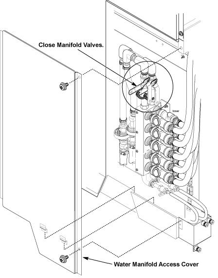
- Remove the water manifold access cover of SC.
- Close the IN/OUT valves of water manifold.
Figure 1. Water Manifold Access Cover and IN/OUT Valves
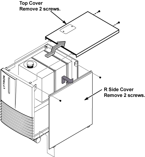
- Remove top cover of LCS by removing 2 screws.
- Remove R side cover of LCS by removing 2 screws.
Figure 2. Cover Removal of LCS
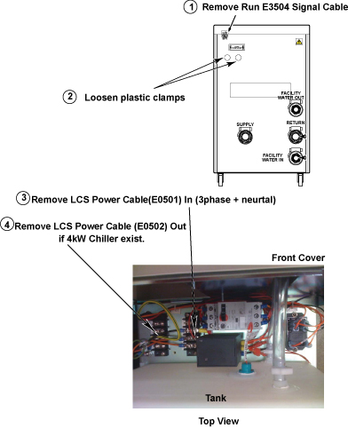
- Disconnect the power and signal cables from LCS.
Figure 3. Power and Signal Cables
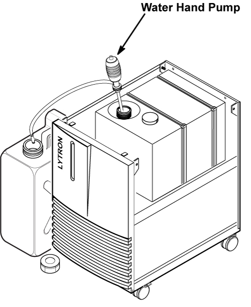
- Set the water hand pump to LCS tank and draining tank.
- Drain the all coolant from LCS tank.
Figure 4. Setting of Coolant Draining
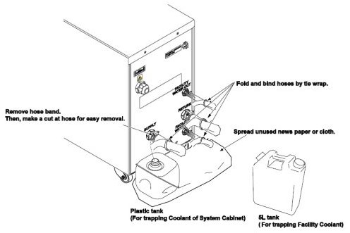
- Before removing the hoses from LCS, fold and bind each hose
to prevent from draining. Spread unused news paper for cloth on the
floor.
Figure 5. BIND EACH HOSE
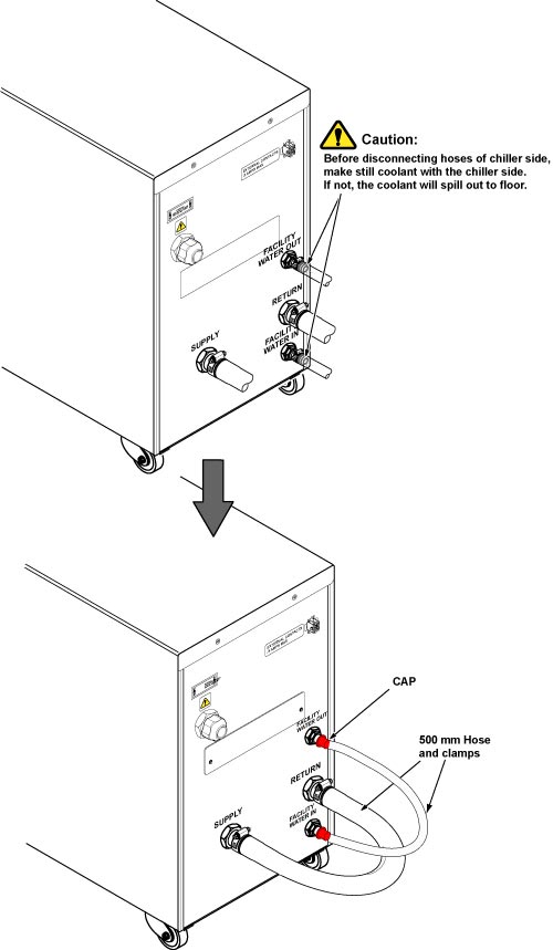
- Disconnect hoses from LCS rear panel.
- notice
- note:Connect 500 mm hose to inlet and outlet of LCS with clamps.
Be careful the coolant does not spill to floor. If needed, use funnel and 5L tank.
Figure 6. Hose Setting of LCS Rear Panel
- Restore the tank cap and covers of LCS.
- Set the new LCS to the site.
- Refill the drained coolant to new LCS tank.
- Restore LCS and SC with reverse order of procedure.
 |
1 Finalization
Procedure
- Verify that four casters are attached on the floor.
- Restore the Power. Refer to Lockout / Tagout for System Cabinet PDU Main Breaker.
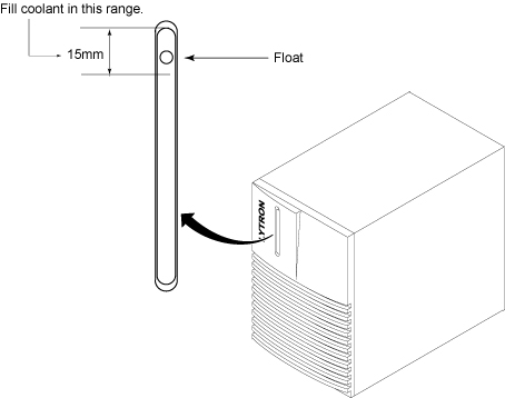
- Check the coolant level by checking that the float is in the range. Refer to #id_13106924/SL986376-1084835.
Figure 7. Coolant Level
- Verify that there is no abnormal sounds or vibration while power is on.
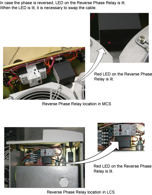
- Verify that LED on Reverse Phase Repay is NOT lit while MCS/LCS is running.
Figure 8. LED on Reverse Phase Repay
- Run one head or body scan.
- Return the defective LCS and tank which was attached with LCS FRU kit.