4kW LCS Replacement
Prerequisites
Procedure
- Remove Front Lower Cover. Refer to SC Cover Removal.
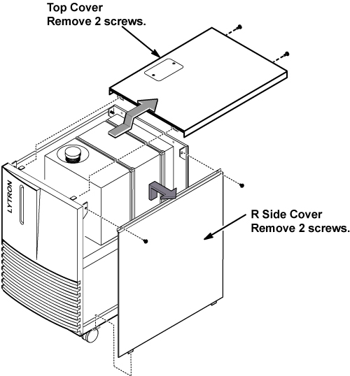
- Remove top cover of LCS by removing 2 screws.
- Remove R side cover of LCS by removing 2 screws.
Figure 1. Cover Removal of LCS
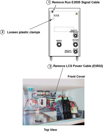
- Disconnect the power and signal cables from LCS.
Figure 2. Power and Signal Cables
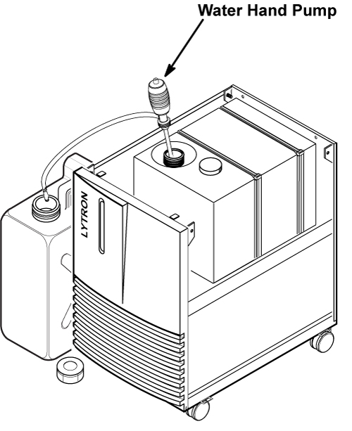
- Set the water hand pump to LCS tank and draining tank.
- Drain the all coolant from LCS tank.
Figure 3. Setting of Coolant Draining
- Before removing the hoses from LCS, fold and bind each hose
to prevent from draining. Spread unused news paper for cloth on the
floor.
Figure 4. BIND EACH HOSE
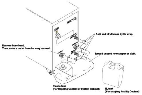
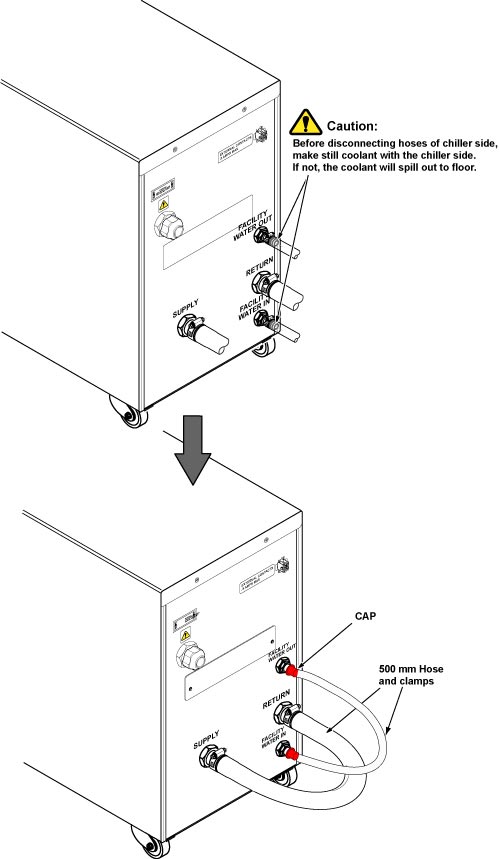
- Disconnect hoses from LCS rear panel.

- notice
note:Be careful the coolant does not spill to floor. If needed, use funnel and 5L tank.
- Connect 500 mm hose to inlet and outlet of LCS with clamps.
Figure 5. Hose Setting of LCS Rear Panel
- Restore the tank cap and covers of LCS.
- Set the new LCS to the site.
- Refill the drained coolant to new LCS tank.
- Restore LCS and SC with reverse order of procedure.
1 Finalization
Procedure
- Verify that four casters are attached on the floor.
- Restore the Power. Refer to Lockout / Tagout for System Cabinet PDU Main Breaker.
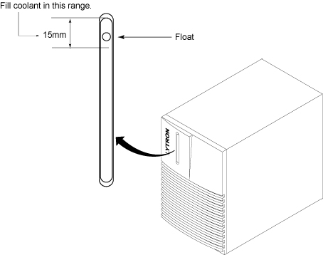
- Check the coolant level by checking that the float is in the range. Refer to #id_13106925/SL986376-1102010.
Figure 6. Coolant Level
- Verify that there is no abnormal sounds or vibration while power is on.
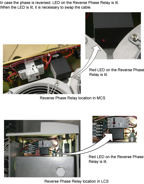
- Verify that LED on Reverse Phase Repay is NOT lit while MCS/LCS is running.
Figure 7. LED on Reverse Phase Repay
- Run one head or body scan.
- Return the defective LCS and tank which was attached with LCS FRU kit.