1.5T HNS NCU Connector Bracket Replacement
Prerequisites
This procedure applies to Revision 3, 1.5T Head, Neck, Spine (HNS) Coils only (refer to rating plate for revision number). It details the replacement of the NCU connector bracket on the posterior portion of the HNU.
Procedure
- notice
- Run the HNS Coil MCQA Tool for the Posterior Head-Face and Posterior Head-Chest Horseshoe TL configurations to verify the coil is functioning properly prior to rework. Refer to 1.5T HNS Coil MCQA Setup to set up the coil.
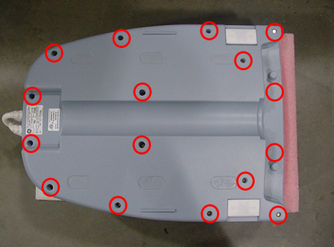
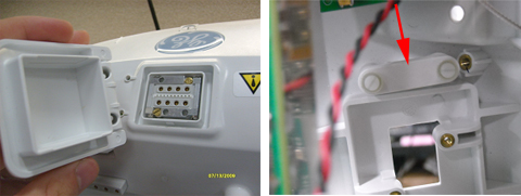
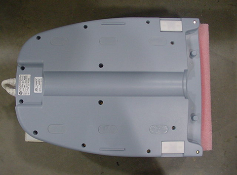
- Remove the bottom cover of Head-Neck unit. Set bottom cover
and the brass screws aside.
Figure 1. Removing Bottom Cover
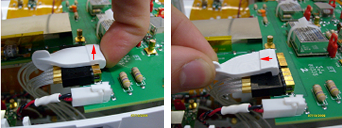
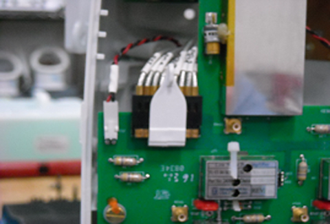
- Unplug NCU Connector RF and DC Cables from the CH11 Feedboard.
- Gently pull up on the RF Connector Retainer, then remove it
by pulling back on the small vertical tab. Set the retainer aside.
Figure 2. Removing RF Connector Retainer
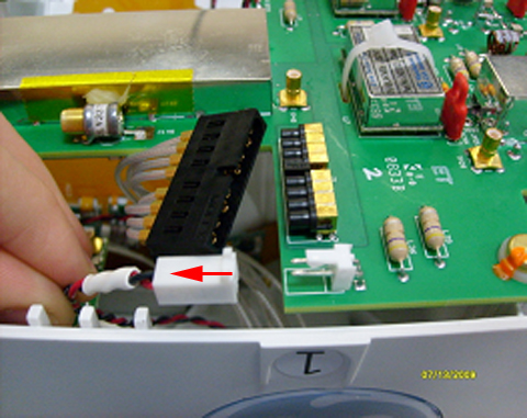
- Unplug the DC Connector by pulling on the white connector housing.
Figure 3. Unplugging DC Connector
- Gently pull up on the RF Connector Retainer, then remove it
by pulling back on the small vertical tab. Set the retainer aside.
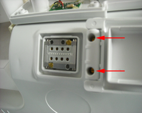
- Using a 1/8 in. slotted screwdriver, remove the two external
screws from the NCU Cover, and set them aside.
Figure 4. Removing Cover Screws
- Remove the NCU Connector cover and inner threaded retainer.
Set these items aside.
Figure 5. Removing NCU Connector Cover and Retainer
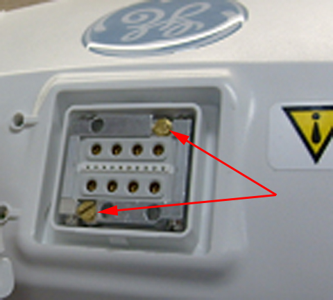
- Remove the two brass screws from the NCU Connector, and set
them aside.
Figure 6. Removing Brass Screws
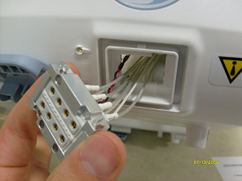
- Remove the NCU Connector by carefully pulling the cables through
the posterior former wall, and set the connector aside.
Figure 7. Removing NCU Connector
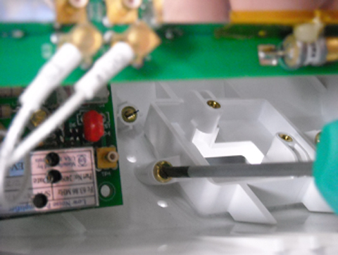
- Using a 6 in. long slotted screwdriver, remove the two mounting
screws from the NCU Bracket. Discard the old bracket and the brass
mounting screws.
Figure 8. Removing NCU Bracket Screws
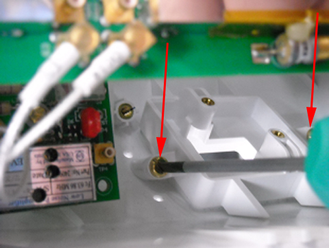
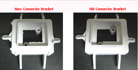
Figure 9. Connector Bracket Identification
- Install the new bracket with the brass screws included in FRU
Kit using the 6 in. long slotted screwdriver.
Figure 10. Installing New Bracket
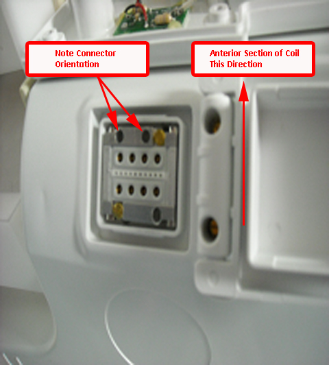
- Reinsert the NCU Connector into the housing, and install using
the two brass screws removed earlier. Tighten the screws until the
connector is fully seated, then tighten an additional one-eighth turn.
Figure 11. Reinserting NCU Connector
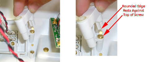
- Reinstall the inner threaded retainer, making sure to orient
it correctly.
Figure 12. Reinstalling Retainer
- While holding the inner threaded retainer, reattach the NCU
cover. Tighten the screws until the cover is fully seated, then tighten
an additional one-eighth turn.
Figure 13. Reattaching NCU Cover
- Reattach the RF and DC cables to the CH11 Feedboard.
Figure 14. Reattaching Cables
- Reinstall the lower cover of the HNS unit using the brass screws
removed earlier.
Figure 15. Reinstalling HNS Cover
 |
Finalization
Verify the coil functionality by running the HNS Coil MCQA Tool for the Posterior Head-Face and Posterior Head-Chest Horseshoe TL Configurations. Refer to 1.5T Head Neck Spine (HNS) Coil MCQA Setup to set up the coil.