Troubleshooting for UPM- Body and Head Functional Check for HDE14.0
This troubleshooting needs to be performed if the failure of UPM Functional Check is related to Over limit or Under limit of peak power.
1 If BODY UPM FUNCTIONAL CHECK IS FAILED
- Edit Upm1Cal1.cfg as following procedure.
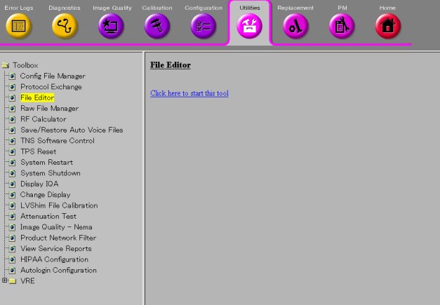
- Open File Editor by selecting Utility/File Editor from Common Service Desktop.
Figure 1. File Editor
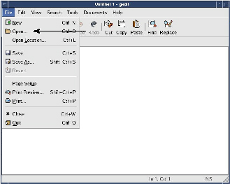
- Select File/Open.
Figure 2. File/Open
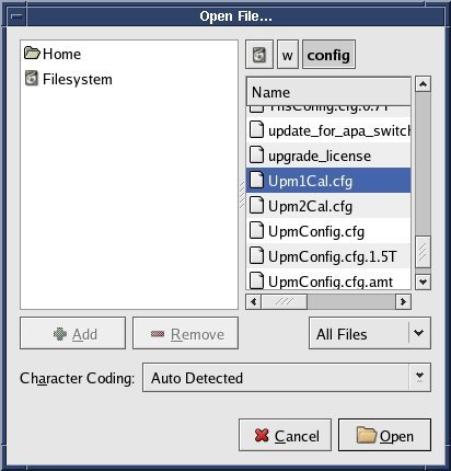
- Select 'w/config/Upm1Cal.cfg' and Open.
Figure 3. Select file
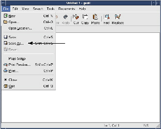
- Select Save As... and save the file as 'Upm1Cal.cfg.bk' .
Figure 4. Save As
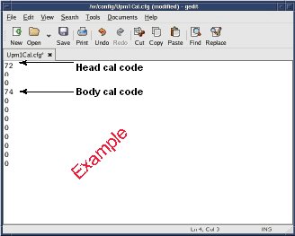
- In case of over peak power, decrease the Body cal code by '1'.
In case of lower peak power, increase the Body cal code by '1'.
Figure 5. Edit
- Save the config file.
Figure 6. Save

- Quit the tool.
- Perform [TPS Reset].
- Open File Editor by selecting Utility/File Editor from Common Service Desktop.
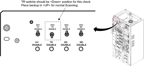
- Inhibit TR faults. Disable the Driver Module. Move switch 2
to the TR Disable position. See Figure 7.
Figure 7.
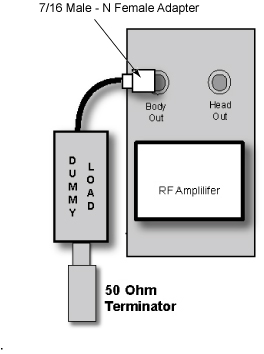
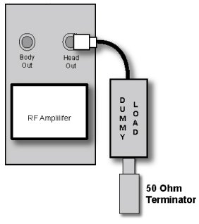
- Remove the Body RF cable from J4. Connect the RF dummy load
into J4. Use 7/16 Male - N Female Adapter attached in System Cabinet.
Figure 8. Plug the Dummy Load into J4, Body Out
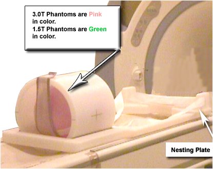
- Place the Body Sphere and Loader on the Nesting Plate as shown
in Figure 9.
Figure 9. SPT Nesting Plate Setup
- Press Align on.
- Move the cradle to place the Laser alignment light on the center of the Body Loader and phantom.
- Press Landmark.
- Press Advance to Scan.
- From the Common Service Desktop:
- Select Calibration Tab
- For the Class A/C service tool, select UPM Tool from the calibration menu and select Click here to start this tool
- Figure 10 shows an example of the UPM tool.
Figure 10. UPM Main Window
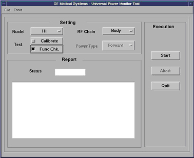
- Select the Nuclei [1H].
- Select the RF Chain you are going to check [Body].
note:
Power Type selection will be grayed out. This is normal, and is not used.
- Select: [Func Chk] Button
- Select the [Start] button.
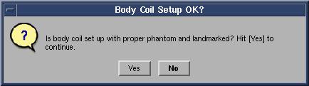
Figure 11. Body Coil Setup Question
- After that, the tool takes full control and runs the 3 functional
tests for whatever setup is currently active. The result of each test
is compared against a Specification File on the system. Status should
indicate Pass/Fail.
During the tests, the user will be prompted 3 times as each test completes. Look in the error log to confirm that the tests completed successfully. The following illustrations show an example of pop ups and error logs that should be seen.
Figure 12. Body Peak UPM Trip Question

Figure 13. Body Pulse Width Trip Question

Figure 14. Body Pulse Duty Cycle Trip Question
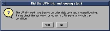
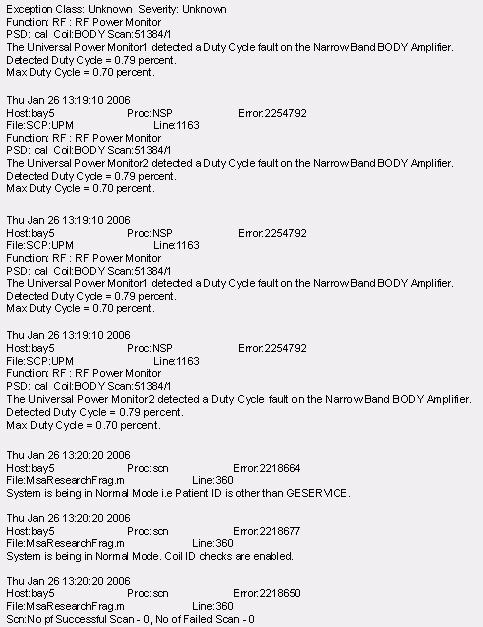
Figure 15. Error Log Example Showing Body Pulse Duty Cycle Trip
 note:
note:A TPS Reset must be preformed when testing is complete before scanning can resume.
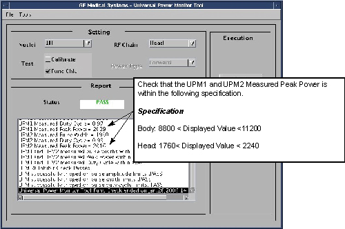
- Check that the Measure Peak Power satisfies the specification.
See Figure 16.
Figure 16. Measured Peak Power
- If measured peak power does not satisfy the specification in Figure 16, go back to If BODY UPM FUNCTIONAL CHECK IS FAILED.
- It the test is passed, restore the Body out cable to SRFD3. Restore Driver Module switch 2 to the TR Enable position
- Perform TPS Reset.
- Perform UPM- Body Functional Check.
2 If Head UPM FUNCTIONAL CHECK IS FAILED
- Edit Upm1Cal1.cfg as following procedure.
- Open File Editor by selecting Utility/File Editor from Common Service Desktop.
Figure 17. File Editor
- Select File/Open.
Figure 18. File/Open
- Select 'w/config/Upm1Cal.cfg' and Open.
Figure 19. Select file
- Select Save As... and save the file as 'Upm1Cal.cfg.bk' .
Figure 20. Save As
- In case of over peak power, decrease the Head cal code by '1'.
In case of lower peak power, increase the Head cal code by '1'.
Figure 21. Edit
- Save the config file.
Figure 22. Save
- Quit the tool.
- Perform [TPS Reset].
- Open File Editor by selecting Utility/File Editor from Common Service Desktop.
- Remove the Head RF cable from J3. Connect the RF dummy load
into J3. Use 7/16 Male - N Female Adapter attached in System Cabinet.
Figure 23. Plug the Dummy Load into J3, HeadOut
- Withdraw the Cradle from its previous position.
- Place the head coil on the cradle.
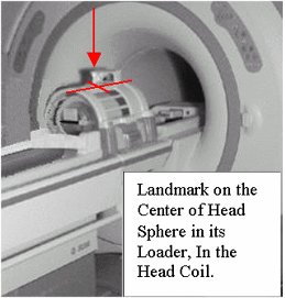
- Insert the Head Sphere and Loader into the Head coil as shown in.
- Press Align on.
- Place the laser alignment light on the center of the Phantom
in the Head coil. Refer toFigure 24.
Figure 24. Landmarking the Head Coil
- Press Landmark
- Press Advance to Scan
- Select the Nuclei 1H
- Select the RF Chain you are going to check Head.
- Select: Func Chk Button
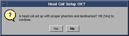
- Select the Start button.
Figure 25. Head Coil Setup. Click [Yes] When The Head Coil Is Ready To Go
- After that the tool takes full control and runs the 3 functional
tests and the UPM status should indicate Pass/Fail.
During the tests, the user will be prompted 3 times as each test completes. Look in the error log to confirm that the tests completed successfully. The following illustrations show an example of pop ups and error logs that should be seen.
Figure 26. UPM Looping Trips
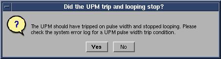
Figure 27. UPM Duty Cycle Loop Trip
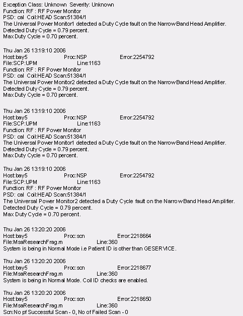
Figure 28. Duty Cycle Look Trip Log Example
- Check that the Measure Peak Power satisfies the specification.
See Figure 29.
Figure 29. Peak Power
- If measured peak power does not satisfy the specification in Figure 29, go back to If Head UPM FUNCTIONAL CHECK IS FAILED.
- It the test is passed, restore the Head out cable to SRFD3. Restore Driver Module switch 2 to the TR Enable position
- Perform TPS Reset.
- Perform UPM- Head Functional Check.
3 Finalization
- Check that cable at SRFD is restored
- Check that SW2 of Driver Module is set to enable.
- Return the system to patient scanning configuration and do a test scan.