|
Symptom in DQA
II Tool Actions Required Window |
Recommendations
|
|
One or more gradients appear not to be functioning
at all.
|
Verify the system can properly scan the head image. See Review DQA II Images to Verify Proper Head Scan. |
|
Z gradient coil appears
to be driven by the wrong gradient input.
|
-
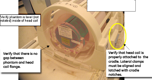
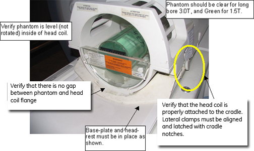
Check coil type (Figure 1 or Figure 2), phantom type
(Table 1), and positioning, coil latches/clamps, landmarking, etc. (Figure 3). If an issue
is found, correct it and run the DQA II Tool again.
-
Review the most recent DQA exam in
the image browser.
-
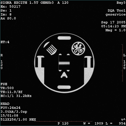
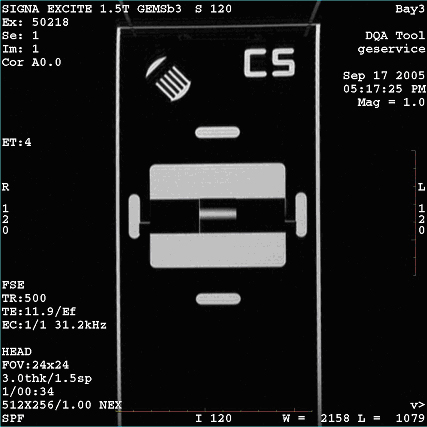
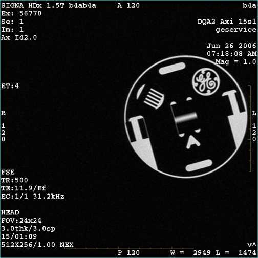
If the latest exam has images labeled Axial (Coronal), make sure at least one of those images
looks similar (shape and position of phantom features) to Figure 4 or Figure 5.
-
If the acquired axial (coronal) image
looks similar to Figure 4 or Figure 5 (even if degraded via low SNR, ghosting, distortion,
etc.), suboptimal image quality may have confused the DQA II Tool.
Resolve the IQ related issues before running DQA II Calibration.
-
If the axial (coronal) image does not look similar to Figure 4 or Figure 5, there may be
a gradient wiring/setup problem. Proceed to the next step to resolve.
-
See Gradient Cabling.
|
|
Z gradient polarity appears to be
inverted.
|
-
Check coil type, phantom type and
positioning, coil latches/clamps, landmarking, etc. If an issue is
found, correct it and run the DQA II Tool again.
-
Review the most recent DQA exam in the image browser.
-
If the latest exam has images labeled Coronal, make sure at least one of those images looks similar
(shape and position of phantom features) to Figure 5.
-
If the acquired coronal image looks
similar to Figure 5 (even if degraded via low SNR, ghosting, distortion, etc.), suboptimal
image quality may have confused the DQA II Tool. Resolve the IQ related
issues before running DQA II Calibration.
-
If the acquired coronal image does not look similar to Figure 5, there may be
a gradient wiring/setup problem. Proceed to the next step to resolve.
-
If the latest exam contains an image
labeled Axial, the DQA II Tool made an early detection
of a Z gradient polarity problem from the set of multi-slice images.
-
If the central bar feature (above arrow
in Figure 4) moves toward the GE logo and comb features
as the slice location moves from INFERIOR to SUPERIOR, the Z gradient
may be polarity flipped. Proceed to the next step.
-
If the bar moves away from the GE logo and comb features, the suboptimal image quality
may have confused the DQA II Tool. Resolve the IQ related issues before
running DQA II Calibration.
-
Review the images in the browser, checking
for an error caused by image degradation such as noise, distortion,
etc. See Figure 4 and Figure 5 for proper images.
-
See Gradient Cabling.
|
|
Phantom used appears to be wrong
and/or severely mispositioned.
|
-
Check coil type, phantom type and positioning,
coil latches/clamps, landmarking, etc. If an issue is found, correct
it and run the DQA II Tool again.
-
Visually verify the phantom is positioned
approximately in the center of the bore before scanning.
|
|
Phantom is offset more than ±36
mm along Z.
|
-
Check coil type, phantom type and positioning,
coil latches/clamps, landmarking, etc. If an issue is found, correct
it and run the DQA II Tool again.
-
Make sure the correct phantom is used,
properly positioned and centered in the head coil and landmarked.
-
Check Laser Light Alignment to ensure that the axial alignment light aims straight
down and lines up with the crosshairs on the DQA phantom.
-
Make sure the isocenter Z value is
close to the default for the magnet type, and verify that the proper
magnet and magnet cover options are properly set in the MR confess file.
|
For any of the following:X and Y gradient coil inputs
appear to be swapped.
X and Y gradient polarities
appear to be inverted.
X gradient polarity appears
to be inverted.
Y gradient polarity appears
to be inverted.
X and Z gradient polarities
appear to be inverted
X gradient polarities appear
to be inverted.
|
-
Check coil type, phantom type and positioning,
coil latches/clamps, landmarking, etc. If an issue is found, correct
it and run the DQA II Tool again.
-
Review the images in the browser, checking
for an error caused by image degradation such as noise, distortion,
etc. See Figure 4 and Figure 5 for proper images.
-
See Gradient Cabling.
|
| For any of the following:
|
-
Check coil type, phantom type and positioning,
coil latches/clamps, landmarking, etc. If an issue is found, correct
it and run the DQA II Tool again.
-
Make sure the correct phantom is used,
properly positioned and centered in the head coil and landmarked.
-
Visually inspect the phantom in the
head coil to verify it is not rotated.
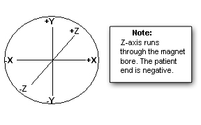
note:
If a positive value is observed for phantom rotation in
the Z direction, rotate the phantom clockwise (when viewing from the
front).
-
Avoid misaligning the phantom (Figure 9) when repositioning.
See Figure 3 for axes information.
|
| For any of the following:
|
-
Check coil type, phantom type and positioning,
coil latches/clamps, landmarking, etc. If an issue is found, correct
it and run the DQA II Tool again.
-
Visually inspect the phantom in the
head coil to verify it is not rotated.
-
If a positive value is observed for
the phantom position in the X direction, move the phantom to the left
(when viewing from the front).
-
If a positive value is observed for
the phantom position in the Y direction, move the phantom down (when
viewing from the front).
-
Avoid misaligning the phantom (Figure 9) when repositioning.
See Figure 3 for axes information.
|