1.5T 4CH Small Flex Coil Troubleshooting
The following tips can be used to troubleshoot common problems with the 1.5T 4CH Small flex coil.
1 Receiving No Signal
• Problem: You are unable to pre-scan or are scanning and yet receiving no signal. • Possible Solution: Refer to the following steps.
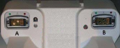
- Verify the green lights above the port A/B are illuminated. This indicates the coil is properly plugged into the system.
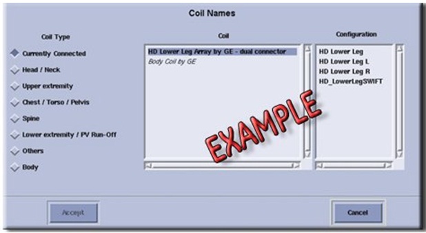
- Verify that the system has correctly detected the coil by checking
in the “Currently Connected” in the GUI to select coils
in Rx as shown in the example in Illustration 1.
Figure 1. Currently Connected Coils Window In The Scan Screen
- Verify that the scan locations and any FOV offsets are correct.
- Verify that the coil is positioned with the cable exiting towards the bore.
- Verify that the cable is not looped or crossed.
There can also be a problem at the system interface port. If you still cannot get a signal, try to scan (transmit and receive) with the body coil. For this test, be sure to remove the imaging coil from the magnet bore before you scan with the body coil. If you still receive no signal the problem probably lies with the MR system. If the scan completes successfully, there is probably a problem with the coil. Contact GE for further assistance. If you are unable to scan with the substitute coil, there may be a system problem related to this particular coil type.
2 Image Quality
Problem: Poor IQ, shaded images, or if MCQA fails. Possible Solution: Refer to the following steps.
- Verify that there are no loops in the cables.
- Verify that there are no metal or ferromagnetic objects close to the coil, patient or magnet (i.e., safety pin, hair pin)
- Verify that the coil is properly positioned
- Verify that your center frequency is within the frequency adjustment range for your system.
- Verify that the R1, R2 and TG values from the pre-scan are
within normally expected ranges.
If you have not done so already, perform the coil Quality Assurance test (refer to Operator’s Manual). If the values you obtain do not fall within normal operating parameters, investigate this further by performing a phantom scan with the body coil. For this test, be sure to remove the imaging coil from the magnet bore before you scan with the body coil. If you still have the same problems, there is probably an MR system problem. If the body coil scan is satisfactory, acquire a scan using another coil of the same type (receive-only, phased array) and. If the image quality is visibly improved, there may be a problem with the coil. Contact GE for further assistance.
3 Artifacts
• Problem: There is a black line or signal void on the image. • Possible Solution: Verify that there is no metal present in the area being scanned in or on the patient.
4 Output Cable Check
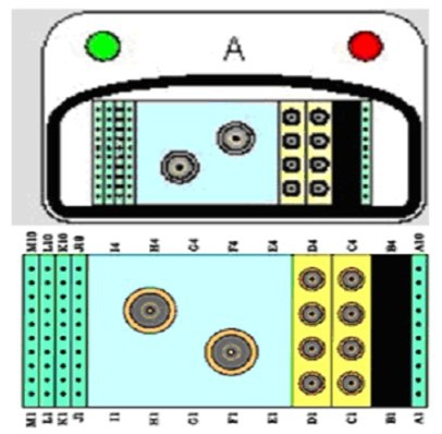
- Visually inspect all coaxial connectors and pins on the coil connector. Illustration 2 shows the pin layouts of the coil connector. The connector of 1.5T 4CH Small Flex Coil has 2 DC pins in column A, 2 DC Pins Column J and 6 DC pins in column M, 4 RF coaxial connector’s columns C. If there are any broken, deformed or recessed pins or coaxial connectors, replace the Coil.
- Visually inspect to ensure the availability of 4 RF coaxial Connectors and 10 DC Pin are available in Cable Connector.
The 1.5T 4CH Small Flex Coil has Port A Connector that is connected to Port A/B of MR System.
Figure 2. Pin Layouts of Hypertonic Connectors A Receptacle
- note:
The center pins of the System Connector receive coaxial connectors are extremely fragile. Do not attempt to make any measurements at these center pins.
5 Coil not recognized on MR System:
- Ensure that the coil is present in Coil database.
- Replace the 1.5T 4CH Small Flex Coil.
6 Finalization
No finalization steps.