VRF Hardware Diagnostics

1 Diagnostic Link

Diagnostics >> System Function >> Recon >> VRF Hardware Diagnostics

Diagnostics >> Hardware Location >> System Cabinet >> Recon >> VRF Hardware Diagnostics

Figure 1. VRF Hardware Diagnostics
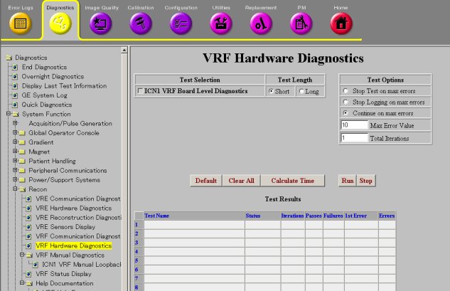
2 Purpose

The purpose of the ICN VRF Board Level Diagnostics is to test the VRF board hardware.

3 Components Tested

  • VRF SRAM

  • DMA engine

  • Filters

  • Registers

  • VRF to IRF interrupt capability

4 Requirements

If the RRX is not working properly, or if unsure about the RRX status, before executing the VRF Hardware Diagnostics, please apply dual fiber optic service loopback connector to replace product cable and prevent interference from the RRX.

Notice Image
  • warning
  • Laser Radiation Hazard!
  • Invisible laser radiation can be emitted from disconnected fiber-optic cables or connectors.
  • Do not stare into the beam, point the cable or connector ends at your eyes, or view through optical instruments.
Notice Image
  • notice
  • The SFP optical transceiver is very sensitive to electrostatic discharge (ESD), SFP latent failures can occur, in dry climates or low relative humidity, surpassing their ESD protection.
  • Contaminant failures can occur in SFP optics and exposed glass Rx and Tx cable ends. Do not touch the exposed ends on fiber connectors. Leave the dust caps in place until you are ready to install the SFP module. Use the Fiber Optics Cleaning Kit to clean both the SFP and cable end every time they are replaced or swapped from one port to another, or when using a loopback.
  • When working with the SFP optical transceiver or SFP Loopback, also observe the following precautions:
    • Always use ESD protection when handling the SFP optical transceiver to prevent early failure.
    • Always keep a protective cap on unplugged fiber connections.
    • The SFP must be shipped in antistatic packaging. Discard any SFP shipped or stored without proper ESD protection.
    For more information on handling and cleaning the SFP transceiver refer to Fiber Optic Cable Devices Installation and Replacement.

5 Test Sequence

  1. Select ICN VRF Board Level Diagnostics from the VRF Hardware Diagnostics screen.

  2. Click Run.

  3. Ensure that the hardware passes the diagnostic by reviewing the status in the Test Results table.

    note:

    If the test fails, note the approximate time. This time is needed to identify the time stamp suffix of the result file.

6 Expected Results

This diagnostic has a passed or failed status. If the diagnostic has failed, please review the error log and corresponding extended error messages for subsequent actions. A failed status does not mean that the VRF is bad. Follow the error message to isolate the fault of the VRF hardware or other processes external to the VRF.