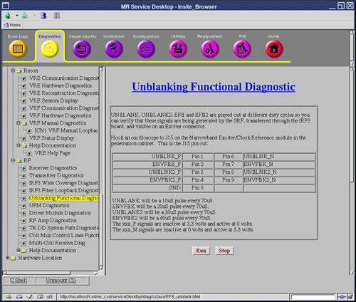
Unblanking Functional Diagnostic
1 Diagnostic Link
Diagnostics >> System Function >> RF >> Unblanking Functional Diagnostic
Diagnostics >> Hardware Location >> System Cabinet >> RF >> Unblanking Functional Diagnostic
Figure 1. Unblanking Functional Diagnostic
2 Purpose
UNBLANK, UNBLANK2, EFB and EFB2 are played out at different duty cycles so you can verify that these signals are being generated by exciter.
3 Components Tested
-
AGP board
4 Requirements
-
AGP board
-
Oscilloscope
5 Test Sequence
-
Remove the cable from the Exciter Front Panel's J15 serial connector.
-
Click Run.
-
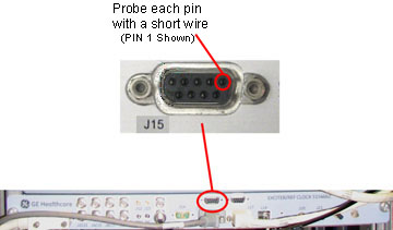
Probe each pin of the J15 connector with a short piece of wire such as a paper clip and connect the probe to the wire to get a reading (see Figure 2).
Figure 2. Exciter Front Panel, J15 Connector
6 Expected Results
Each pin should have a reading as noted below.
-
UNBLANK will be a 10µS pulse every 70µS.
-
ENVFBK will be a 20µS pulse every 70µS.
-
UNBLANK2 will be a 30µS pulse every 70µS.
-
ENVFBK2 will be a 40µS pulse every 70µS.
-
The xxx_P signals are inactive at 3.3 volts and active at 0 volts.
-
The xxx_N signals are inactive at 0 volts and active at 3.3 volts.
note:Cycle Tolerance = +/- 2µS