MCD Volt Diagnostic
1 Diagnostic Link
Diagnostics >> System function>> RF>>Driver Module Diagnostics
2 Purpose
This test outputs changing voltage levels from Driver module measurement by the FE.
3 Components Tested
Driver Module Lite.
4 Requirements
Digital Multimeter
Digital Oscillograph
5 Block Diagram
None.
6 Expected Results
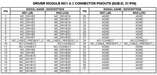
The muilticoil bias line voltages can be also measured at the J5 or J10 connectors on the front of the Driver Module Lite. See Figure 1 for the pinout identification of connectors J5 and J10.
Figure 1. Pin-Out ID for J5 & J10 Connectors
7 Etcetera
Test Delay sets the length of time that each port is tested during each test set.
Un-blank Time is not used during this test since the TR bias voltage is always at a positive polarity un-blank level and never transitions to a negative polarity blank level.
8 Links
<<< Driver Module Help document >>>