MCD Channel Enable Diagnostic
1 Diagnostic Link
Diagnostics >> System function>> RF>>Driver Module Diagnostics
2 Purpose
This test exercises all multicoil ports 1 to 16 one at a time during 3 different test sets. The multicoil bias voltage on all the ports is initially set to the enable voltage (negative polarity) level.
3 Components Tested
Driver Module Lite.
4 Requirements
Digital Multimeter
Digital Oscillograph
5 Block Diagram
None.
6 Test Sequence
The first test set, starting at port 1, sequentially transitions the TR bias voltage on each multicoil port from -5V to 3V and then back to -5V. This is repeated until all remaining 15 ports have been exercised in this manner.
The next test set, starting at port 1, sequentially transitions the TR bias voltage on each multicoil port from -5V to 5V and then back to -5V. This is repeated for all the remaining 15 ports.
The last test set, starting at port 1, sequentially transitions the TR bias voltage on each multicoil port from -5V to 7V and then back to -5V. This is repeated for all the remaining 15 ports. After the conclusion of the last test set, the test process ends.
7 Expected Results
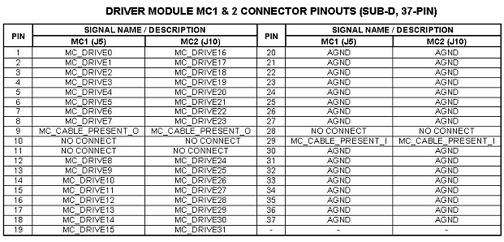
The muilticoil bias line voltages can be also measured at the J5 or J10 connectors on the front of the Driver Module Lite. See for the pinout identification of connectors J5 and J10.
Figure 1. Pin-Out ID for J5 & J10 Connectors
8 Etcetera
Test Delay sets the time in seconds that the outputs will remain at a given voltage level. The levels will transition from 3V to 5V to 7V.
Since the output levels remain constant over the time specified in the Test Delay and are not blanked or un-blanked, the Un-blank Timeis not used for this test.
9 Links
<<< Driver Module Help document >>>