Gather Load Data Diagnostic
1 Diagnostic Link
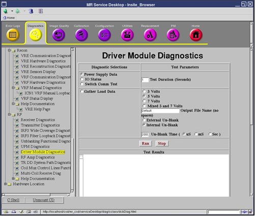
Diagnostics >> System Function >> RF >> Driver Module Diagnostics
Diagnostics >> Hardware Location >> System Cabinet >> Driver Module Diagnostics
Figure 1. Driver Module Diagnostics
2 Purpose
This test checks the current draw on the Dynamic Disable (DD) and the Transmit/Receive (TR) bias lines.
3 Components Tested
-
Driver Module
-
LPCA
-
Cables
-
Connectors
-
Coil (if connected)
4 Requirements
None
5 Test Sequence
Refer to Table 1 Coil Parameters Matrix for the test voltage.
The data is sampled five (5) times for each line and then written to two (2) text files in /usr/g/service/log. You can then use the “more” or “cat” commands to view the contents of these files.
6 Expected Results
The data in each file is reported in Open (forward bias) and Short-circuit (reverse bias) modes. These modes refer to the fault conditions for which the Driver Module is always monitoring.
Values much greater than the typical values may indicate circuit damage or a short-circuit condition somewhere in the bias path. Values much less than the typical values may indicate circuit damage or an open-circuit (maybe a disconnected cable) condition somewhere in the bias path. Refer to Table 1 Coil Parameters Matrix for the typical values.
Run this test to troubleshoot intermittent problems and collect baseline data on any new surface coil. If troubleshooting one of these two scenarios, refer to the System Block Diagrams to help isolate the fault.