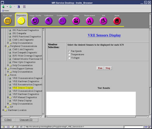
This diagnostic displays the sensor values for all ICNs installed
in the system. Three categories of sensor values are displayed: Fan Speeds, Temperatures, and Voltages. The display format includes the ICN number,
sensor name, value and units, minimum value, maximum value, critical
value and whether critical values were exceeded.
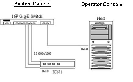
3 Requirements
All Ethernet cables must be connected from the Host to the Ethernet
switch.
All Ethernet cables must be connected from the ICN to the Ethernet
switch.
ICN is powered on.
4 Block Diagram
Figure 2. VRE Hardware Communication Block Diagram
5 Test Sequence
Verify that all Ethernet cables are
connected per Requirements.
Execute the diagnostic by selecting
the desired sensors.
Verify that the sensor values display
for all configured ICNs.