Power Supply Data
1 Diagnostic Link
Diagnostics >> System Function >> RF >> Driver Module Diagnostics
Diagnostics >> Hardware Location >> System Cabinet >> Driver Module Diagnostics
Figure 1. Power Supply Data
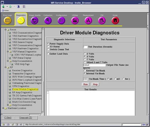
2 Purpose
This diagnostic reads the Power Supply information from the DCB board every five (5) seconds for the specified Test Duration (max 300 secs).
3 Components tested
Driver Module
4 Test sequence
This diagnostic reads the Power Supply information from the DCB board every five (5) seconds for the specified Test Duration (max 300 secs). The values are checked against the tolerances listed in the DcbConfig.cfg file.
5 Results
Any failing values will be printed out in red. Passing values will be printed out in blue.
 |
|
No error messages will be logged for failing power supplies since the Applications Code will be logging these errors automatically.