IRF3 BLD
1 Diagnostic Link
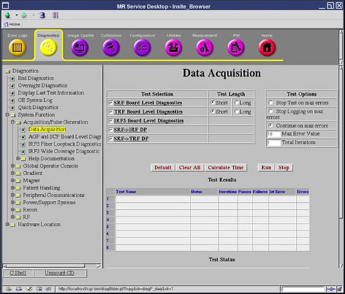
Diagnostics >> System Function >> Acquisition/Pulse Generation >> Data Acquisition
Diagnostics >> Hardware Location >> System Cabinet >> CAM >> Data Acquisition
Figure 1. IRF3 BLD
2 Purpose
The IRF3 Board Level Diagnostic tests the circuitry internal to the IRF3 board. The test is run from the AGP board that accesses the IRF3 board over the cPCI bus.
3 Components Tested
-
The internal memory buffers of the IRF3.
-
The internal data paths of the IRF3.
-
The logic state machines of the IRF3.
4 Requirements
None
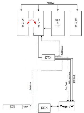
5 Block Diagrams
Figure 2. IRF3 Block Diagram
6 Test Sequence
-
Select IRF3 BLD from the Data Acquisition screen.
-
Click Run.
-
Review the Test Results table to see if the diagnostic passed or failed.
7 Expected Results
Output values are judged pass or fail. In the event of failure, the details of the failure can be found in the GE System Log.