I/O status
1 Diagnostic Link
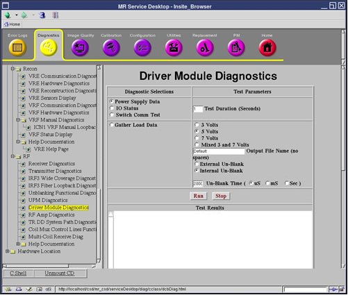
Diagnostics >> System Function >> RF >> Driver Module Diagnostics
Diagnostics >> Hardware Location >> System Cabinet >> Driver Module Diagnostics
Figure 1. Driver Module Diagnostics
2 Purpose
The test will display:
- Front Panel Interface
- Un-Blank Cable
- Un-Blank Harness
- High Voltage Switch
- Fan 1
- Fan 2
- MCD 1 (always blue)
- TR/DD
- MCD1 Cable (always blue)
- MCD2 Cable (always red since it is NOT PRESENT)
- Head Overtemp
- Body Overtemp
- MSN Overtemp
- CAN Board
- CAN ISO 5 Volts
- CAN Flash 5 Volts
- DCB Reset State
3 Components Tested
- Driver Module
4 Requirements
None
5 Test Sequence
- Select I/O Status from the Driver Module Diagnostics screen.
- Click Run.