DTX BLD
1 Diagnostic Link
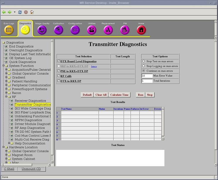
Diagnostics >> System Function >> RF >> Transmitter Diagnostics
Diagnostics >> Hardware Location >> System Cabinet >> Transmitter Diagnostics
Figure 1. DTX BLD
2 Purpose
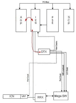
The DTX BLD tests the fiber link between the DTX and the IXG3, and the circuitry internal to each DTX module. Every system has a narrowband exciter (DTX). The DTX module also contains a clock reference module that produces a very accurate 80MHz clock signals and an 112 MHz LO signal.
3 Components Tested
-
The fiber link between each DTX module and the IXG board.
-
The programmable registers and logic internal to the DTX.
4 Requirements
Run and pass the IXG BLD before running DTX BLD.
5 Block Diagrams
Figure 2. DTX Block Diagram
6 Test Sequence
-
Select DTX Board Level Diagnostics from the Transmitter Diagnostics screen.
-
Click Run.
-
Review Test Results table to see whether the diagnostics passed or failed.
7 Expected Results
Output values are judged pass or fail. In the event of failure, the details of the failure can be found in the GE System Log.