4ch Torso Phased Array Coil for HDe 1.5T
1 INTRODUCTION
1.1 How the Torso Phased Array Coil Operates
The coil consists of four loops. An anterior portion contains two critically overlapped loops, while a posterior portion contains another two critically overlapped loops. The primary application is the imaging of the abdomen and lower body. See
Figure 1. TORSO ARRAY FUNCTIONAL BLOCK DIAGRAM
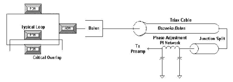
The torso multicoil is a four-loop array designed to obtain the higher SNR of smaller MRI surface coils and retain a large field of view. Also, because the array is split in two halves (one in the front and one in the back) there is a volume effect that increases the SNR at the center of the body. Each half consists of two individual loops that are approximately 12 inches (30.5 cm) by 8 inches (20.3 cm) with a 1.75-inch (4.5 cm) overlap. This translates to a coil area of approximately 14 inches (35.6 cm R/L) by 12 inches (30.5 cm S/I) overall for each half.
The array is intended to be used in one mode only, using all four coils.
The interface to Signa HDe is a Hypertronics connector and is keyed for a specific field strength use only. The two halves are cabled to each other.
The array is designed for feet-first torso imaging. This implies a cable length of approximately 85 inches (216 cm).
The only active components, including the PIN diodes, are on the input boards via an access cover over the input circuitry of the coil. The PIN diodes may be replaced in the field.
Each coil loop must be turned off during transmit. This is accomplished by the active blocking network, which includes a tuned L-C network and a single PIN diode per coil element.
The input capacitor is chosen such that the transmit blocking impedance (at 250 mA DC bias to the diode) is greater than 1K ohm. The coil loop size is 12 inches (30.5 cm) X 8 inches (20.3 cm) which is 96 in*in (620 cm*cm).
The input capacitor is chosen for both matching and blocking circuitry. The blocking circuitry and matching circuit reside on the Torso Phased Array Input Board.
In addition to the active blocking components there are two passive decoupling networks (PDN) for each loop. These PDNs provide both heat distribution for UFI pulse sequence compatibility as well as improve the coil safety in case of an active network failure. The PDNs are not serviceable by field personnel.
A shielded resonant cable trap on each loop minimizes the ground currents on the shield due to its high impedance.
A 50-ohm phase shift network ensures a multiple of a half wavelength from the 30-pin connector to the coil input. This phase compensation network takes into account cable lengths and the balun circuit. The phase shift networks for all four loops reside on the Torso Phase Adjust Board located in the Quick Disconnect Enclosure which is sealed.
1.2 Compatibility
The Torso Phased Array Coil is compatible with the following hardware configurations:
-
Signa HDe 1.5T System
 |
|

1.3 Organization of this Document
This manual is divided into the following sections:
-
Introduction, describes how the Torso Phased Array Coil operates, and when and where it can be used.
-
Setup and Calibration, describes installation procedures.
-
Functional Checks, describes the normal power-up sequence.
-
Replacement / Maintenance, describes field maintenance procedures.
-
Renewal Parts, lists field replaceable parts
1.4 Environmental Requirements
Transport and store the Torso PA coil under the following environmental conditions only, for a period not exceeding 4 weeks:
-
Ambient temperature of –40 degrees C to +60 degrees C with a relative humidity of 10% to 100%. (Non-Condensing)
-
Atmospheric pressure of 765 hPa to 1011 hPa.
Operate the coil in the scanner room only.
2 SETUP AND CALIBRATION
2.1 Checking the Shipping List - Preliminary
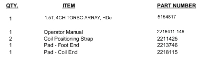
Figure 2 lists theM3335ST 1.5T HD 4CH TORSO ARRAY parts. Check that all parts have been shipped.
Figure 2. 1.5T TORSO PHASED ARRAY COIL SHIPPING LIST
2.2 Installing the Torso Phased Array Coil
Key is used by the operator to select TORSOPA (elements 1-4) imaging. Name the key TORSOPA. See Figure 3.
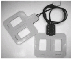
Figure 3. TORSO ARRAY COIL
2.3 Functional Checks
-
Perform a body coil scan SNR verification. Refer to Section 3-1, BODY COIL SNR VERIFICATION.
-
Perform a Torso Phased Array coil SNR verification. Refer to Section 3-2, TORSO PHASED ARRAY COIL SNR VERIFICATION.
2.4 Periodic Quality Assurance Check
On a periodic basis, such as during planned maintenance, perform the quality assurance checks outlined below to ensure that the coil is operating properly:
-
Check the external cable and coil foam for cracks or breaks once a week. Refer to Section 4-5, CHECKING THE CABLES.
-
Perform a coil SNR verification. Refer to Section 3-2, TORSO ARRAY COIL SNR VERIFICATION.
-
Record the date and value calculated in Section 3-3, SNR IMAGE ANALYSIS in column 2 under "SNR Data QA Check" of the Data Table as instructed.
-
As is instructed in the Data Table, divide the SNR value obtained in the periodic QA check by the original SNR value and record in column 6 of the Data Table.
-
If this ratio is not greater than 85%, then there may be a problem in the coil system. Contact your local GE Service Representative.
3 FUNCTIONAL CHECKS
3.1 Body Coil SNR Verification
An alternate proprietary procedure is available for GE use, and to customers with a valid Advanced Service Package Limited License. Refer to TLT PROCEDURE located on appropriate proprietary Service Methods CD-ROM, navigate to System: Troubleshooting.
Phantom Required
-
SPT Short Loader w/ SPHERE ASM 2125244
Setup Procedure
|
|
-
Remove Quad Head Coil (if present) from cradle.
-
Select [New Exam] to allow a new landmark to be set.
-
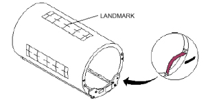
Position the Body Phantom in the center of the Body Loader at the center of the cradle. Landmark the center of the phantom and advance to isocenter using the [ADVANCE TO SCAN] button. See Figure 4.
Figure 4. BODY PHANTOM/LOADER LANDMARK SETUP
Scan
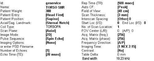
Figure 5. Protocol
-
Setup Scan Prescription as shown in Figure 5.
-
Select [Auto Prescan] to properly calibrate the RF power level for the 90 degree and 180 degree pulses.
-
Select [Scan]. Observe the resulting images. Ensure that there are no artifacts of any sort in the resulting image. Record the Exam number and Series number for SNR Calculations.
-
Select [Scan] again. This second image will be used for determination of Body Coil mode SNR.
-
Select [Cancel]. Refer to Section 3-3 for SNR image analysis.
3.2 Torso Phased Array Coil SNR Verification
An alternate proprietary procedure is available for GE use and to customers with a valid Advanced Service Package Limited License. Refer to "TLT PROCEDURE" located on appropriate proprietary Service Methods CD-ROM, navigate to System:Troubleshooting.
Phantom Required
-
SPT Short Loader w/ SPHERE ASM 2125244
Setup Procedure
|
|
-
Select [New Exam] to allow a new Landmark to be set.
-
Remove Quad Head Coil (if present) from cradle.
-
Place Torso Phased Array Coil to be tested around the body loader/body phantom with the torso coils placed on the top and bottom side of loader. See Figure 6. Use positioning straps provided with Torso Phased Array Coil.
-
Connect Torso Phased Array Coil connector to its mating connector in the Carriage Assembly.
-
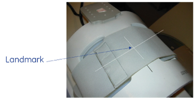
Position the Cardiac Array/loader in the center of the cradle. Landmark for center of head phantom and advance to isocenter using the [ADVANCE TO SCAN] button. See Figure 7.
Figure 6. TORSO ARRAY/BODY LOADER SETUP
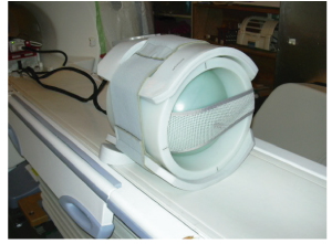
Figure 7. TORSO ARRAY/BODY LOADER LANDMARK
Scan
Figure 8. Protocol
-
Setup Scan Prescription as shown in Figure 8
-
Select [Auto Prescan] to properly calibrate the RF power level for the 90 degree and 180 degree pulses.
-
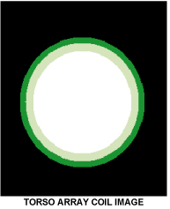
Select [Scan]. Observe the resulting image of the sphere. SeeFigure 9 (normal image). Ensure that there are no artifacts of any sort in the sphere image. Record the Exam number and Series number for SNR Calculations.
-
Select [Scan] again. This second image of the sphere will be used for determination of Cardiac mode SNR.
-
Select [Cancel]. Refer to Section 3-3 for SNR image analysis.
Figure 9. TORSO ARRAY COIL IMAGE
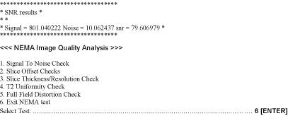
3.3 SNR IMAGE ANALYSIS
Description
The SNR Tool retrieves two operator selected images. Signal value is computed as the mean pixel value in a ROI covering 80% of the image. The image is analyzed to determine the center for positioning the ROI. A difference image is created by subtracting the second image from the first and to calculate noise from the subtracted image. Signal value, noise value, and SNR are reported.
SNR Image Analysis Procedure
1. Select [Service Desktop], [Calibration/Checks], then [Image Quality].
2. According to the following illustrations , check SNR.
Figure 10.
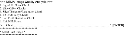
Figure 11.
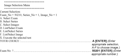
Figure 12.
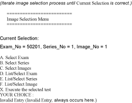
Figure 13.
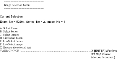
Figure 14.
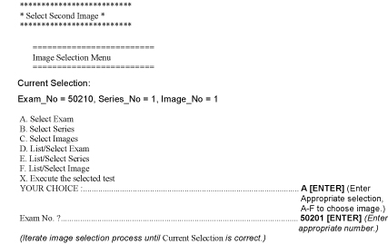
Figure 15.
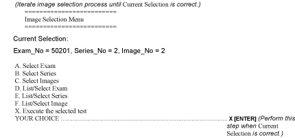
Figure 16.
3. Record the date and value calculated in the appropriate column under "SNR Data QA Check" of the Data Table. Refer to DATA TABLE.
4 REPLACEMENT AND MAINTENANCE
4.1 Disassembly/Reassembly of Torso Array
Figure 17. TORSO ARRAY
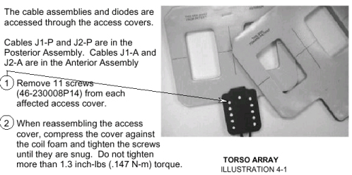
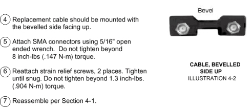
4.2 Replacing the External Cable
Figure 18. CABLE ACCESS
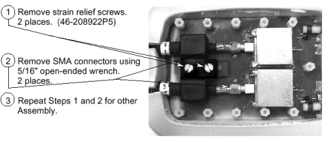
Figure 19. CABLE, BEVELLED SIDE UP
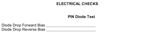
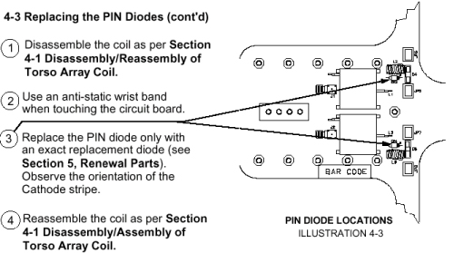
4.3 Replacing the PIN Diodes
|
|
Antenna is tuned at the factory to provide the proper input impedance. Circuit board is not field replaceable. PIN diodes are the only field replaceable components on the circuit board.
Figure 20. PIN DIODE LOCATIONS
4.4 Replacing the Mechanical Hardware
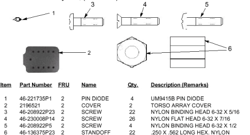
Refer to Section 5, Renewal Parts, for Torso Phased Array Coil part numbers. Cable Screws, Hexagonal Standoffs, Access Cover, Access Cover Screws, and Standoff Screws can all be replaced.
See Section 4-1 for the Disassembly/Reassembly of Torso Array. To replace the Hexagonal Standoffs, 46-136375P23, and Standoff Screws, 46- 208922P23, carefully pull back foam from around Torso Phased Array Input Board to expose the Standoff Screws. Remove any broken pieces and replace with new components. Tighten until snug. Do not tighten beyond 1.3 inch-lbs. (.147 N-m) torque.
See Section 4-1 for the Disassembly/Reassembly of the Torso Array.
4.5 Checking the External Cable
Check the external cables for cracks or breaks once each week. Replace the external cable per Section 4-2, Replacing the External Cable if any damage or wear is found.
See Section 5, Renewal Parts, for the cable part number.
4.6 Cleaning the Coil
|
|
Clean the Torso Array Coil and external cable with a mild dishwashing liquid and water solution. Wet a soft cloth with the solution and proceed to clean. The Torso Array Coil can be cleaned with a 10% bleach solution. Wet a soft cloth with the solution and proceed to clean.
The coil should be cleaned before and after shipping, during planned maintenance, and as determined by the field engineer or customer.
Figure 21. Torso Phased Array Coil
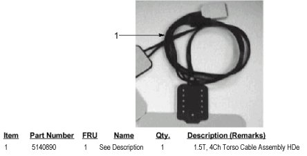
Figure 22. Torso Phased Array Coil
Figure 23. Torso Phased Array Coil
5 DATA TABLE
Figure 24. Data Sheet
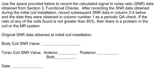
Figure 25. SNR Check
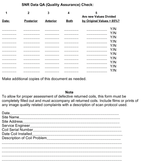
Figure 26. Electrical Check