4CH WRIST ARRAY
1 INTRODUCTION
1.1 Product Identification and Shipping List
This is a service manual for 4CH WRIST ARRAY
1.2 Compatibility
This coil is compatible with the following hardware configurations:
-
Signa HDe 1.5T System
-
Optima MR360/ Brivo MR355
1.3 Related Documentation
-
1.5T HD 4Ch Wrist Array Operator manual, 5145565-3
1.4
Storage Requirements
The coil should be stored in the Scanner Room. The coil dimensions and weight represent the coil, vertical holder and baseplate combined. The phantom dimensions represent the phantom and phantom holder combined. The phantom weight represents the phantom, filled with fluid, and the phantom holder combined.
Dimensions
Coil Dimensions: 214.8 mm x 438.0 mm x 356.0 mm 8.59 in x 17.52 in x 14.24 in
Phantom Dimensions: 81.5 mm x 152.4 mm x 65.0 mm 3.26 in x 6.10 in x 2.60 in
Weight
Coil Weight: 5.2 kg 11.44 lbs.
Phantom Weight: 0.596 kg 1.31 lbs.
1.5 Theory of Operation
The Phased Array High Resolution Wrist Coil consists of one coil with 4 elements. Two quad birdcages provide four channels. Each channel contains items 1, 2, and 3. Item 1 is a tuning and decoupling circuit, which uses passive decoupling via back to back fast acting diodes which are enabled by the RF pulses. When the diodes short, the network creates a high impedance block to eliminate decoupling artifact and interaction with the excitation field. Item 2 is a tuning and matching circuit which not only tunes and matches the coil to the system resonant frequency and matches the coil to 50 ohms when loaded, it also provides DC bias routing through birdcages to decouple the coil during transmit. Item 3 provides the proper phase shift between the preamplifier and item 2 to create the phased array decoupling required during receive.
2 SETUP AND CALIBRATION
2.1 Coil Installation
The name for this coil is: HRWRIST
Add the coil using the Configuration File Manager. Refer to: Service Methods CD; System Level Procedures; Software Utilities.
2.2 Installation Functional Checks
-
Perform system level Signal to Noise Check. Refer to Service Methods CD; System Level Procedures; Functional Checks; Signal to Noise Check.
-
Perform Section 3 – Coil Imaging Performance Verification.
2.3 Periodic Quality Assurance Check
On a periodic basis, such as during planned maintenance, perform the quality assurance checks as outlined below to ensure the coils is operating properly.
-
Check external cable for cracks or cuts.
-
Perform Section 3 – Coil Imaging Performance Verification and record data values in Data Sheet.
3 FUNCTIONAL CHECKS
3.1 Scanner Verification
Perform system level Signal to Noise Check. Refer to Service Methods CD; System Level Procedures; Functional Checks; Signal to Noise Check.
3.2 Coil Imaging Performance Verification
3.2.1 Tools Required
3.2.2 Explanation of Procedure
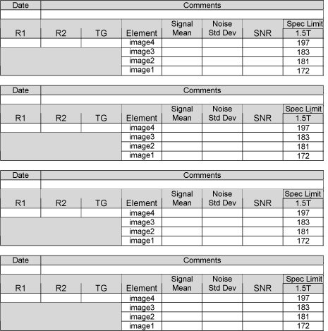
The 1.5T/1.0T High Resolution Wrist Coil is used in 1 mode of operation and has 1 coil name: HRWRIST. Since the HRW is a 4 channel phased array coil, SNR measurement requires 4 sets of signal and noise scans. Refer to the Data Sheet in Appendix 7-1 to understand the data required to calculate the individual element SNR for each mode of operation. All ROI measurements are made on the individual element images, not on the composite image.
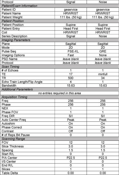
The image quality check uses two different protocols for signal and noise image acquisition. The signal scan is an FSE sequence used to minimize susceptibility and B0 inhomogeneity effects. The noise scan is a GRE sequence that has a Control Variable (do_noise) to eliminate the transmit RF completely during the scan. The signal scan must be run prior to the noise scan as the R1, R2, and TG values from the signal scan are used for the noise scan.
3.2.3 Signal Scan
-
From the Scan Desktop, start new scan by selecting [New Pt]; set Patient ID to “geservice” and Patient Weight to “111” pounds. Click [Patient Position] to open protocols window.
-
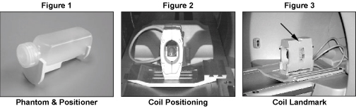
Remove any other surface coils from the cradle. Position the High Resolution Wrist Coil, in the vertical configuration, and Baseplate on the cradle with the coil cable extending into the magnet [Figure 2]. Place the phantom on the phantom positioner and insert them into the coil as illustrated in Figures 1 and 2.
-
At the magnet, press “Alignment Light” button to turn on the light. Move the cradle to align the coil to the alignment lights as shown in Figure 3. Press “Landmark” button to landmark the alignment.
-
Move the coil to scan position by pushing the “Move to Scan” button, ensuring cable does not get snagged.
-
At the console, set the protocols per the Signal section from Table 3-2-4: Signal and Noise Protocols.
-
Click [Save Series] to download the protocols, then click [Prepare to Scan].
-
Open [Display CVs] menu under [Research Operations] (click right mouse button). Set the “saveinter” CV to “1” (saves the intermediate images so ROI measurements can be performed).
-
Run [Auto Prescan]. Record the R1, R2 and TG values on the SNR Data Sheet (found at the end of this manual).
-
Run [Scan].
Figure 1. Phantom Positioning
3.2.4 Noise Scan
A signal scan must be run prior to the noise scan as the same R1, R2 and TG values must be used for both the signal and noise scans. Do not run an Auto Prescan prior to the noise scan as the values will be changed.
-
Copy the signal scan series. Use [Copy Series] (highlight signal series and click right mouse button) and [Paste Series] in RX Manager.
-
Click [View Edit] and set the protocols per the Noise section from Figure 2Signal and Noise Protocols.
-
Click [Save Series] and click [Prepare to Scan].
-
Open [Display CVs] menu under [Research Operations]. Set the “saveinter”, “rhformat”, and “do_noise” CVs to “1”.
-
Run [Manual Prescan], do not make any changes, and click [Done].
-
Run [Scan].
Figure 2. SIGNAL AND NOISE PROTOCOLS
3.2.5 SNR Image Analysis
SNR Measurement
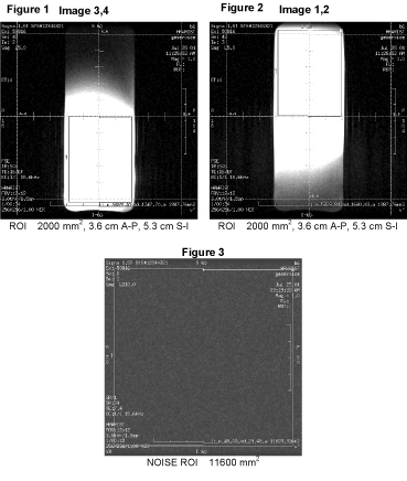
For the signal measurement, choose a rectangular ROI covering the appropriate section of the phantom for the receiver channel being scanned. Rectangular ROI should be about 2000 mm2. ROIs are shown in Figures 1 through 3 below.
The SNR shall be calculated using the signal to noise ratios of the individual receiver channels. Individual receiver SNR is defined as the mean of data within the signal ROI divided by the standard deviation of data within the noise ROI:
SNR= Signal Mean / Noise SD
Figure 3. SNR Measurement
Individual Element Performance
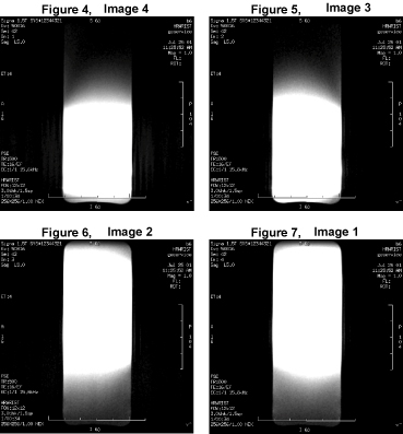
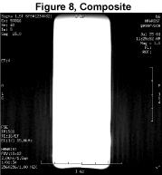
Regions of interest in both signal and noise images can be measured directly in the image browser. Click the user interface button Measure, select the circular or rectangular shape, and adjust its size and orientation when the shape is displayed in the selected image. Mean, standard deviation, and area of the ROI will appear in the lower right corner of the image. Examples of typical Receiver Images are shown in Figures 4 through 8 below.
Figure 4. SNR Measurement
SNR Specification
The SNR measurements must be greater than or equal to the following specifications:
Figure 5. SNR Specification
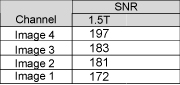
SNR= Signal Mean / Noise SD
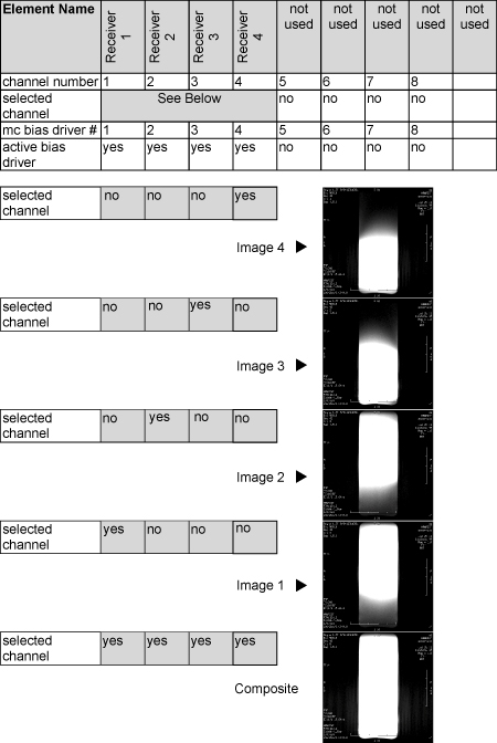
3.2.6 Troubleshooting Tips
If poor image quality or dead channels are present, use the following setup information and compare the resulting images to isolate any defective part(s).
Figure 6. TROUBLESHOOTING
4 MAINTENANCE
4.1 Coil Care
 |
|

|
|
4.2 Special Care Requirements
None
5 REPLACEMENT
Simple removals that are clearly obvious are not described here.
Unless otherwise noted, the steps for re-assembly are simply the reverse order of the steps described for disassembly.
External Cable Replacement
The 1.5T HD 4Ch Wrist Array external cable is not field replaceable.
6 RENEWAL PARTS
6.1 Field Replaceable Units
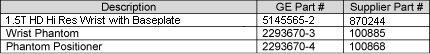
Figure 7. 1.5T FIELD REPLACEABLE UNITS LIST
6.2 Other Replaceable Accessories
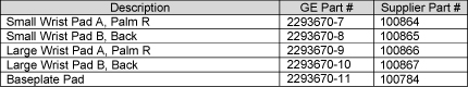
Figure 8. OTHER REPLACEABLE ACCESSORIES LIST
7 SNR Data Sheet
Figure 9.