1.5T HD 8 Channel Neurovascular Array Replacements
1 Personnel Requirements
2 Overview
Follow this process to replace field replaceable units for the 1.5T HD 8 Channel Neurovascular Array by Invivo. (M3335M)
3 Tools and Test Equipment
For cable replacement, a ¼ inch flat blade screwdriver.
For superior and right/left latch replacement, a ¼ inch flat blade screwdriver and a #2 Philips screwdriver.
4 Replacement Parts
Refer to the FRU Document.
5 Procedure
5.1 Cable Functionality
5.1.1 Cable Continuity Check
To Be Performed by Authorized Service Engineer Only. See the Coil Troubleshootingprocedure.
5.1.2 Cable Replacement Procedure
 |
|
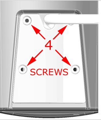
The 4 coil connector mounting screws are located at the superior end of the coil. Remove the 4 coil connector mounting screws as detailed in Figure 1. Remove the coil connector by pulling away from the coil in the superior direction.
Figure 1. Remove 4 Screws
The steps for installation of the new cable are simply the reverse order of the steps described for removal.
5.2 Mechanical Parts Replacement
5.2.1 Mechanical Hardware Check
Exercise the superior and right/left coil latches. The latches must move smoothly and lock positively into place. The latches must not loosen or open during the course of an examination.
5.2.2 Mechanical Replacement of Hardware
Disassembly of Anterior Coil Section
In order to perform the following procedures:
-
Replacement of Right/Left Latch.
-
Replacement of Superior Latch.
it will be necessary to remove the anterior coil cover from the anterior coil section.
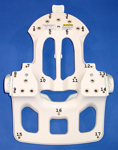
1. Loosen, but do not remove, the 17 screws that fasten the anterior coil cover to the anterior coil section. The 17 fastener locations are detailed in Figure 2.
Screws numbered 5, 6, 10, 11, and 16 are longer than the other screws. See Figure 2.
Figure 2. Anterior Coil Fastener Locations
2. Carefully lift the anterior coil section away from the anterior coil cover.
3. Place the anterior coil section aside, being careful to keep the screws stored in their respective holes.
4. During FRU replacement and cover reinstallation, assure that the electronics in the anterior coil section are not disturbed.
5. The steps for cover reinstallation are simply the reverse order of the steps described for removal.
Replacement of Right/Left Latch
In order to perform the Replacement of the Right/Left Latch, it will be necessary to remove the anterior coil cover from the anterior coil section. Follow the procedure detailed in Mechanical Replacement of Hardware, Disassembly of Anterior Coil Section, then continue below.
1. Open the Right/Left Latch Assembly FRU package, and find the FRU Replacement Instructions, illustrated in Figure 3.
Figure 3. Right/Left Latch Assembly FRU Replacement Instructions
585184.pdfReplacement of Superior Latch
In order to perform the Replacement of the Superior Latch, it will be necessary to remove the anterior coil cover from the anterior coil section. Follow the procedure detailed in Mechanical Replacement of Hardware, Disassembly of Anterior Coil Section, then continue below.
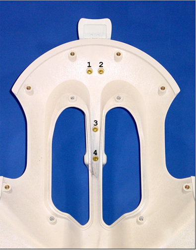
1. Remove the 4 screws that fasten the superior latch assembly to the anterior coil cover. The 4 fastener locations are detailed in Figure 4.
Figure 4. Superior Latch Assembly Fastener Locations
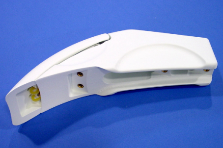
2. Replace the superior latch using the Superior Latch Assembly FRU, see Figure 5.
Figure 5. Superior Latch
5.3 Coil Replacement
No instructions are required.